UIM344 Pulse & Direction Closed-Loop Stepper Motor Controller
UIM344 Pulse & Direction Closed-Loop Stepper Motor Controller — complete technical reference. Full specs, wiring diagrams, pinout, parameter configuration, and sample code.
The UIM344 series from UIROBOT are closed-loop integrated stepper motors comprised of stepper motor, incremental encoder, driver, and closed-loop controller. These motors interface with user controllers, PLCs, or computers through a simple 3-wire pulse-direction interface — making it ideal for applications where traditional pulse control is preferred. With the embedded encoder and closed-loop controller, these motors can perform accurate positioning even under stalling situations. Missing step compensation is done by the motor itself.
This page is the **technical reference** for the UIM344 controller platform used in the [PM Series](/docs/ttl-pulse-direction). For product selection, pricing, and ordering information, see the PM Series overview.
---
## Key Features
:::grid{cols=2 style=card}
**Closed-Loop Control**
Real-time position feedback with automatic missing step compensation. Eliminates lost steps common in open-loop stepper systems, ensuring reliable positioning even under overload conditions.
**Pulse-Direction Interface**
Simple 3-wire control (PULSE, DIRECTION, ENABLE) compatible with most PLCs and motion controllers. No CAN bus configuration required — just connect and go.
**Microstepping Resolution**
Full step to 1/128 microstep, configurable via UART. Default is 1/32 microstep. Ensures smooth, vibration-free motion at low speeds.
**High Performance**
Max speed up to 3000 RPM (model dependent), high positioning accuracy, and fast response time.
:::
:::grid{cols=2 style=card}
**Wide Supply Voltage**
12–24 VDC for NEMA 8 and NEMA 11 models; 24–48 VDC for NEMA 17 and larger. Flexible integration into various power architectures.
**Optically Isolated Inputs**
All logic inputs are optically isolated for noise immunity in industrial environments. Compatible with 3.3V, 5V, and up to 24V signals.
**Adjustable Parameters**
Working current, idle current rate, microstepping, and maximum missing steps configurable via UART interface using the free CFG344 configuration tool.
**Protection Built-In**
Overcurrent, overvoltage, and overtemperature protection standard across all models.
:::
---
## Product Lineup
The UIM344 series covers five motor frame sizes from NEMA 8 to NEMA 34, with optional brake variants for NEMA 17 and above.
### Motor Specifications
| Model | Frame Size | Holding Torque | Rotor Inertia | Rated Current | Supply Voltage | Brake | Encoder | Weight |
|-------|-----------|---------------|--------------|--------------|---------------|-------|---------|--------|
| UIM2040PM | NEMA 8 (20 mm) | 0.038 N·m | 2.9 g/cm² | 0.6 A | 12–24 VDC | — | Incremental | 95 g |
| UIM2852PM | NEMA 11 (28 mm) | 0.16 N·m | 18 g/cm² | 0.8 A | 12–24 VDC | — | Incremental | 232 g |
| UIM4247PM | NEMA 17 (42 mm) | 0.43 N·m | 75 g/cm² | 1.68 A | 24–48 VDC | — | Incremental | 441 g |
| UIM4247PMB | NEMA 17 (42 mm) | 0.43 N·m | 75 g/cm² | 1.68 A | 24–48 VDC | Embedded | Incremental | 533 g |
| UIM5756PM | NEMA 23 (57 mm) | 1.26 N·m | 300 g/cm² | 2.8 A | 24–48 VDC | — | Incremental | 830 g |
| UIM5756PMB | NEMA 23 (57 mm) | 1.26 N·m | 300 g/cm² | 2.8 A | 24–48 VDC | Embedded | Incremental | 1010 g |
| UIM8696PM | NEMA 34 (86 mm) | 6.5 N·m | 1900 g/cm² | 6 A | 24–48 VDC | — | Incremental | 3200 g |
| UIM8696PMB | NEMA 34 (86 mm) | 6.5 N·m | 1900 g/cm² | 6 A | 24–48 VDC | Embedded | Incremental | 3800 g |
### Step Angle
| Parameter | Value |
|-----------|-------|
| Intrinsic step angle | 1.8° |
| After microstepping (1/128) | 0.0140625° |
:::tip
For order code structure, see the [PM Series product overview](/docs/ttl-pulse-direction).
:::
---
## Technical Specifications
### Control Interface
| Parameter | Specification |
|-----------|---------------|
| Control method | 3-wire: Pulse, Direction, Enable |
| Input isolation | Optically isolated |
| Compatible voltages | 3.3V / 5V / 24V (with 2.49kΩ resistor) |
| Minimum pulse width | > 3 μs (high and low level) |
| Maximum pulse frequency | Up to 200 kHz (model dependent) |
| Configuration | UART interface (via CFG344 tool) |
### Motor Drive
| Parameter | Specification |
|-----------|---------------|
| Control method | PWM constant current |
| Microstepping | Full, 1/2, 1/4, 1/8, 1/16, 1/32, 1/64, 1/128 |
| Max speed | Up to 3000 RPM (model dependent) |
| Phase current | Up to 8A (configurable via UART) |
| Low-speed behavior | Vibration-free, noise-free operation |
### Motion Control
| Parameter | Specification |
|-----------|---------------|
| Control modes | Closed-loop position, velocity |
| Features | Missing step self-compensation, stall detection |
| Position accuracy | Encoder feedback, no lost steps |
### Configuration
| Parameter | Range | Default |
|-----------|-------|---------|
| Micro-Stepping | 1, 2, 4, 8, 16, 32, 64, 128 | 32 |
| Working Current | 0.1–8.0 A | Motor dependent |
| Idle Current Rate | 0–100% | 50% |
| Max Missing Steps | 0–65535 | Motor dependent |
### Environmental
| Parameter | Specification |
|-----------|---------------|
| Operating temperature | -40°C to +85°C |
| Storage temperature | -50°C to +150°C |
| Humidity | < 80% RH, no condensation |
| Vibration | 3G Max |
| Protection | Overcurrent, overvoltage, overtemperature |
---
## Control Interface
### Signal Description
| Pin | Name | Function | Description |
|-----|------|----------|-------------|
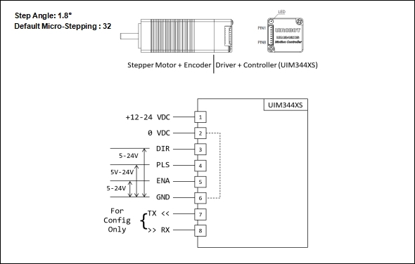
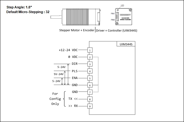
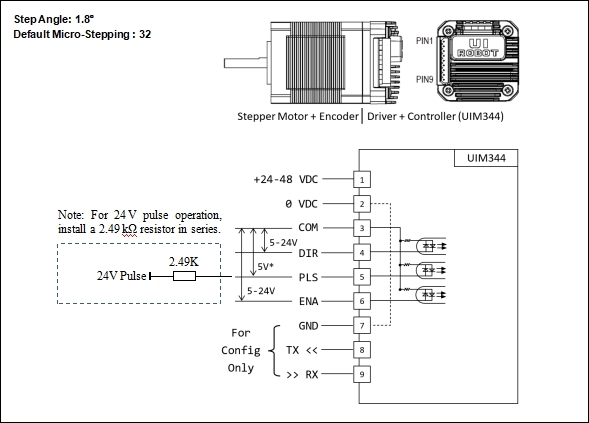
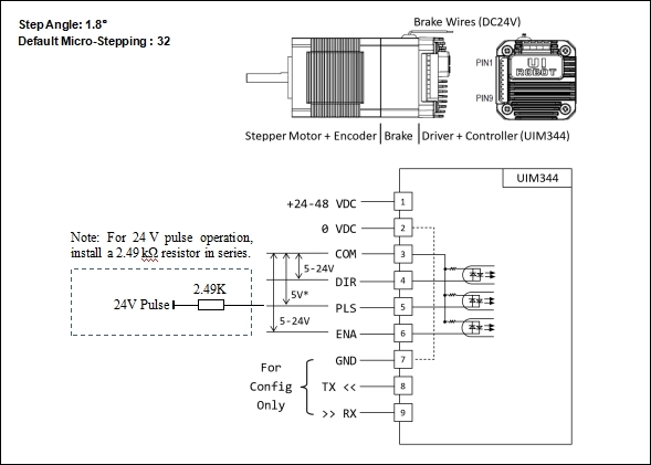
| 1 | V+ | Supply Voltage | 24–48 VDC (UIM344) / 12–24 VDC (UIM344S/XS) |
| 2 | GND | Ground | Supply voltage ground |
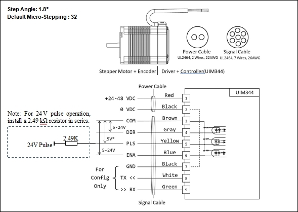
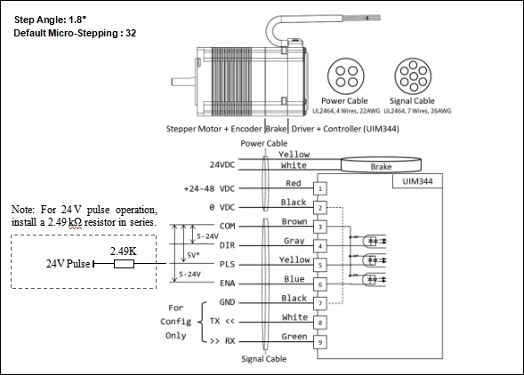
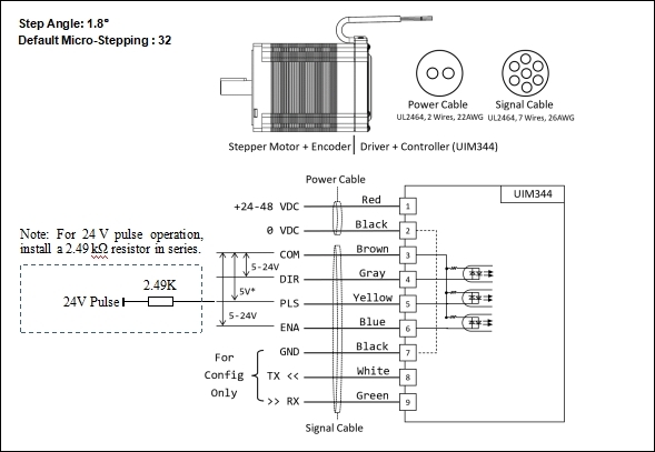
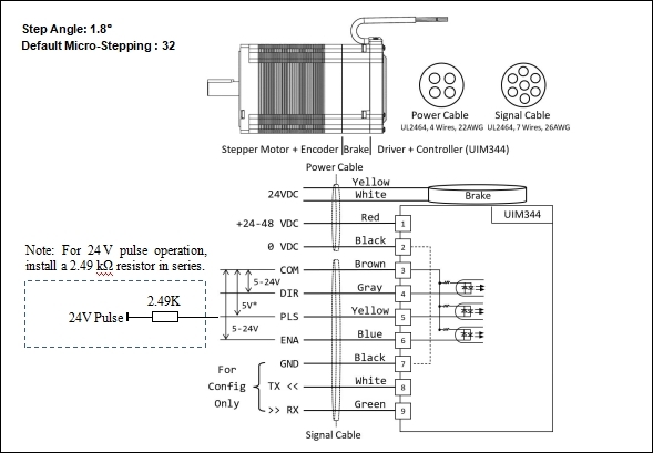
| 3 | COM | Opto-coupler Common | Common anode for opto-isolators (UIM344 only) |
| 4 | DIR | Direction Input | HIGH = CW, LOW = CCW |
| 5 | STP | Pulse Input | Each pulse = one microstep |
| 6 | ENA | Enable Input | HIGH = enabled, LOW = disabled |
### Pulse Rate vs Speed
The required pulse rate (PPS) is calculated as:
```
PPS = (RPM × 200 × MCS) / 60
Where:
MCS = Micro-stepping Resolution (1, 2, 4, 8, 16, 32, 64, 128)
RPM = Revolutions Per Minute
PPS = Pulses Per Second
```
| Motor Speed | 1/8 Microstep | 1/32 Microstep | 1/128 Microstep |
|-------------|---------------|----------------|-----------------|
| 100 RPM | 267 PPS | 1,067 PPS | 4,267 PPS |
| 500 RPM | 1,333 PPS | 5,333 PPS | 21,333 PPS |
| 1000 RPM | 2,667 PPS | 10,667 PPS | 42,667 PPS |
| 3000 RPM | 8,000 PPS | 32,000 PPS | 128,000 PPS |
---
## Wiring Diagrams
### UIM344XS (NEMA 8)
### UIM344S (NEMA 11)
### UIM344 (NEMA 17/23/34)
### Optically Isolated Input Interface
| Input Voltage | Resistor Required | Current |
|---------------|-------------------|---------|
| 5V | None | 5–20 mA |
| 3.3V | None | 5–20 mA |
| 24V | 2.49kΩ in series | ~10 mA |
---
## Driver Parameter Configuration
Parameters are configured via UART interface using the free **CFG344** configuration tool.
### Configuration Steps
1. Connect PC to UIM344 via USB-UART converter
2. Open **CFG344** (UIM344 Config Tool)
3. Select COM port and click OPEN
4. Click GET to read current parameters
5. Modify parameters as needed
6. Click SET to write parameters to EEPROM
7. Reboot the motor to apply changes
:::warning
Do NOT change parameters when the motor driver is ON. Motor must be powered during configuration.
:::
---
## Quick Start
### Step 1 — Connect Hardware
1. Connect power supply (12–24 VDC or 24–48 VDC depending on model)
2. Wire PULSE, DIRECTION, and ENABLE signals from your controller
3. **Double-check all wiring before powering on**
### Step 2 — Configure Motor (Optional)
1. Connect USB-UART converter to UIM344
2. Open CFG344 tool and configure parameters
3. Reboot motor to apply changes
### Step 3 — Send Pulses
### Step 4 — Verify Operation
1. Motor should rotate smoothly without vibration
2. Verify direction matches DIR signal
3. Test enable/disable functionality
---
## Applications
:::grid{cols=3 style=card}
**CNC Machines**
Precise positioning for milling, routing, and engraving. Closed-loop control ensures accurate part dimensions without lost steps.
**3D Printers**
Reliable layer-to-layer positioning. Missing step compensation prevents print failures and improves print quality.
**Packaging Machinery**
Consistent indexing and positioning for labeling, filling, and wrapping operations. High speed capability for production throughput.
:::
---
## Safety Precautions
### Electrical Safety
| Hazard | Precaution |
|--------|------------|
| High Voltage | Disconnect power before wiring. Use within specified voltage range only. |
| Short Circuit | Ensure proper wire gauge and insulation. Install a fuse on the power input line. |
| Grounding | Properly ground the controller to prevent electrical shock and noise interference. |
### Operational Safety
| Hazard | Precaution |
|--------|------------|
| Overheating | Ensure adequate ventilation. Operating temperature: -20°C to +70°C. |
| ESD | Use anti-static precautions when handling. Discharge static before touching terminals. |
| Mounting | Secure the device firmly. Do not operate with loose mounting. |
### Mechanical Safety
| Hazard | Precaution |
|--------|------------|
| Moving Parts | Keep clear of rotating shafts during operation. Wait for motor to stop before handling. |
| Load Limits | Do not exceed rated torque and speed limits to prevent mechanical damage. |
| Coupling | Ensure proper alignment between motor shaft and load to avoid vibration and wear. |
## Related Products
| Product | Description |
|---------|-------------|
| [PM Series](/docs/ttl-pulse-direction) | Product family overview and order code information |
| CM Series | CAN bus smart motors with incremental encoder |
| CA Series | CAN bus smart motors with absolute encoder |
| UIM342 | CAN bus motion controller |
| UIC320A | USB to CAN 2.0B adapter |
---
## Resources
:::tip
Download CFG344 configuration tool, user manuals, and sample code from the [UIROBOT Download Center](https://www.uirobot.com/serve/list-437.html).
:::
- **User Manual** — UIM344 V6.03
- **Configuration Tool** — CFG344
- **Sample Code** — Arduino, C#, Python
- **2D / 3D Drawings** — STEP and DXF formats
---
*Last Updated: 2026-06-25 | Based on UIM344 User Manual V6.03*