UIM342A CAN Bus Smart Servo Stepper Motor Controller
UIM342A CAN Bus Smart Servo Stepper Motor Controller — complete technical reference. Absolute multi-turn encoder, interpolated motion control, CAN 2.0B, wiring, and instruction set.
# UIM342A — CAN Bus Smart Servo Stepper Motor Controller
The UIM342A series are advanced motion controllers designed for servo stepper motors, featuring a CAN Bus interface and **Absolute Multi-Turn Encoder**. These controllers integrate several key functional modules: **Communication Unit / Motion Control Unit / Motor Driver / Feedback Control Unit / Input Logic Control and DSP System**. All control loops are executed within **1 millisecond**, ensuring high responsiveness.
This page is the **technical reference** for the UIM342A controller platform used in the [CA Series](/docs/ca-series). For product selection, pricing, and ordering information, see the CA Series overview.
---
## Product Overview
### Key Features
- **Absolute Multi-Turn Encoder** with internal rechargeable battery
- **High-Performance DSP System**: Executes all control loops within 1 millisecond
- **Comprehensive SDK**: Includes SDK, DLL, LIB, and SO files
- **Sample Codes**: Available in C++, C#, and other languages
- **Cross-Platform Support**: Compatible with Linux, Windows 32-bit, and 64-bit systems
---
## Product Models
The UIM342A series offers three size variants to fit different NEMA standard motors:
| Parameter | UIM342A | UIM342SA | UIM342XSA |
|-----------|---------|----------|-----------|
| **Supply Voltage** | 16-48 VDC | 12-28 VDC | 12-28 VDC |
| **Peak Current** | 1/2/4/8 A | 1/2/4/8 A | 1/2/4/8 A |
| **Micro-Stepping** | 1/2/4/8/16/32/64/128 | 1/2/4/8/16/32/64/128 | 1/2/4/8/16/32/64/128 |
| **Controller Size** | 42×42 mm | 34×34 mm | 20×20 mm |
| **Compatible Motors** | NEMA 17/23/34 | NEMA 17 | NEMA 8/11 |
:::tip
For the order code structure and motor specifications, see the [CA Series product overview](/docs/ca-series).
:::
---
## Core Functions
### Control System
- Robust DSP hardware platform
- Fault tolerance, fail-safe user interface
- Input and event change notification
### Motion Control
- **Interpolated Motion**: Multi-axis coordination with PVT/PT control
- Speed control and position control
- High positioning accuracy, high response
- Maximum speed up to **3000 RPM** (depending on motor type)
- **Backlash Compensation** function
- **Stall Detection** function
### Motor Driver
- Wide voltage input: 24~48 VDC (depending on controller)
- Adjustable phase current: up to 8 A
- Micro-stepping resolution: 1~1/128
- No vibration or noise at low speeds
- Protection: overcurrent, overvoltage, overheating
### Absolute Encoder
- Resolution: single 16-bit, multi-turn 32-bit (±2³¹ Turns)
- Embedded rechargeable battery, standby 1+ year, lifetime 50+ years
- 1.9μA ultra-low standby power consumption
### I/O Logic Control
- 3 Digital Inputs, 1 Output (5V / 50mA)
- Input change notification
- **13 Programmable Actions** can be attached to I/O trigger
### CAN Networking
- Active CAN 2.0, up to 1 Mbps
- 3 types of IDs (Node ID, Group ID, Global ID) for synchronized motion
### Other Features
- Emergency lockdown
- Integrated design with motor
- Aluminum alloy casing, sturdy and durable for easy heat dissipation
- Size as small as 20 mm × 20 mm × 16 mm
---
## Technical Specifications
### Absolute Maximum Ratings
| Parameter | Specification |
|-----------|---------------|
| Ambient temperature under bias | -40°C ~ 85°C |
| Storage temperature | -65°C ~ +150°C |
| V+ with respect to V- (UIM342XSA/342SA) | 10V ~ 30V |
| V+ with respect to V- (UIM342A) | 12V ~ 50V |
| Voltage on input ports with respect to V- | -0.3V ~ 5.3V |
| Maximum current sourced by output port | 100 mA |
| CANH/CANL voltage with respect to V- | -40V ~ +40V |
### Operating Conditions (at ambient temperature 25°C)
| Parameter | UIM342XSA | UIM342SA | UIM342A |
|-----------|-----------|----------|---------|
| Supply Voltage | 12V-28V | 12V-28V | 16V-48V |
| Driver Capacity | Peak 1/2/4/8 A | Peak 1/2/4/8 A | Peak 1/2/4/8 A |
| Current Control | PWM constant current | PWM constant current | PWM constant current |
| Micro-Stepping | 1/2/4/8/16/32/64/128 | 1/2/4/8/16/32/64/128 | 1/2/4/8/16/32/64/128 |
| Operating Temperature | -40°C ~ 85°C | -40°C ~ 85°C | -40°C ~ 85°C |
| Humidity | < 80% RH, no condensation | < 80% RH, no condensation | < 80% RH, no condensation |
| Vibration | 3G Max | 3G Max | 3G Max |
### Communication Interface
| Parameter | Specification |
|-----------|---------------|
| Protocol | CAN 2.0B |
| Physical Layer | Two-wire system, CANH, CANL, twisted pair |
| CAN Driver | Max. 1 Mbps |
| Standard | Meets ISO-11898 standard physical layer requirements |
---
## Interpolated Motion Control
The UIM342A supports **PVT (Position-Velocity-Time)** and **PT (Position-Time)** interpolated motion for precise multi-axis coordination.
### PVT Motion
PVT motion allows you to define position, velocity, and time for each segment, enabling smooth and precise motion profiles.
| Instruction | Description |
|-------------|-------------|
| `MP[i]` | PVT Motion Parameter (queue level, mode, time interval) |
| `PV=X` | Set PVT Motion start index |
| `QP[N]=X` | Set Position value of PVT queue row N |
| `QV[N]=X` | Set Velocity value of PVT queue row N |
| `QT[N]=X` | Set Time interval of PVT queue row N |
| `QF` | Quick Feed PVT data (position, velocity, time in one command) |
### PVT Motion Modes
| Mode | Description |
|------|-------------|
| **Single Mode** | Execute PVT table once |
| **Loop Mode** | Repeat PVT table continuously |
| **FIFO Mode** | First-In, First-Out queue management |
### PT Motion
PT motion uses position and time intervals for simpler motion profiles.
| Instruction | Description |
|-------------|-------------|
| `PT[N]=X` | Set Position value of PT queue row N |
| `MP[4]=X` | Set time interval for PT motion (ms) |
---
## CAN Network & ID Configuration
The UIM342A uses Active CAN 2.0B hardware and software, with CAN bit rate configurable from 125K to 1000Kbps by instructions.
To improve coordination performance of multi-modules, UIM342A supports **3 types of CAN ID**:
| ID Type | Description |
|---------|-------------|
| **Global ID** | Fixed as 0, all devices respond |
| **Group ID** | Configurable via instructions, for group synchronization |
| **Node ID** | Configurable via instructions, for single device addressing |
UIM342A will accept messages that have a CAN ID matching any of the three IDs.
> **WARNING**: Ensure that Group ID1 ≠ Group ID2 ≠ Node ID1 ≠ Node ID2 ≠ Node ID3 ≠ Node ID4 ≠ Node ID5
---
## Motion Control Modes
### JOG Mode (Velocity Mode)
Suitable for continuous speed control applications.
| Instruction | Description |
|-------------|-------------|
| `JV=N` | Set desired speed and switch to velocity mode |
| `BG` | Begin motion |
| `ST` | Stop motion |
### PTP Mode (Position Mode)
Suitable for precise positioning applications.
| Instruction | Description |
|-------------|-------------|
| `PR=N` | Set relative target position |
| `PA=N` | Set absolute target position |
| `SP=N` | Set PTP speed |
| `BG` | Begin motion |
### Acceleration & Deceleration Control
| Instruction | Description |
|-------------|-------------|
| `AC=N` | Set acceleration |
| `DC=N` | Set deceleration |
| `SS=N` | Set cut-in speed |
| `SD=N` | Set stop deceleration |
---
## I/O Logic Control
UIM342A supports 3 digital inputs. Users can configure actions to be performed on logic level changes.
Each input port has **2 sets of motion parameters**: one for rising edge, another for falling edge. Each parameter set includes: Acceleration AC, Deceleration DC, ±Speed SP, ±Displacement PR, ±Position PA.
### 13 Programmable Trigger Actions
| Code | Action Description |
|------|-------------------|
| 0 | Turn Motor Driver Off (Free wheel) |
| 1 | Emergency stop (using SD) |
| 2 | Decelerating to stop (using DC) |
| 3 | Set origin then go reversed relative position (using \|PR\|, SP, AC, DC) |
| 4 | Set origin then Emergency stop (using SD) |
| 5 | Set origin then decelerate to stop (using DC) |
| 6 | Reversed Jog (using \|SP\|, AC, DC) |
| 7 | Jog (using SP, AC, DC) |
| 8 | Go reverse relative position (using \|PR\|, SP, AC, DC) |
| 9 | Go relative position (using PR, SP, AC, DC) |
| 10 | Go absolute position (using PA, SP, AC, DC) |
| 11 | Turn Motor Driver Off + Lock Down control system (inquiry only) |
| 12 | Emergency stop + Lock Down control system (inquiry only) |
### Logic After Motor Stall
After "motor stall" is detected, the motor shaft will be stopped and locked by default. Set `IL[16]=1` to change the logic to "turn motor driver off (freewheel)" after stall detection.
---
## Real-Time Notification
UIM342A can automatically send messages to the user after detecting preset events. The time from detection to feedback is less than **1 millisecond**.
Supported real-time notification events:
- Reach desired position (in PTP mode)
- Rising edge and falling edge of input 1, 2, and 3
- Detection of motor stall
- Other alarm/warnings
---
## Instruction Set Overview
### System Instructions
| Mnemonic | Control Word | Function | Description |
|----------|--------------|----------|-------------|
| `PP[i]` | 0x01 | Set/Get | Protocol Parameters |
| `IC[i]` | 0x06 | Set/Get | Initial Configuration |
| `IE[i]` | 0x07 | Set/Get | Information Enable |
| `ML` | 0x0B | Get | Model |
| `SN` | 0x0C | Get | Serial Number |
| `ER[i]` | 0x0F | Clear/Get | Error Report |
| `QE[i]` | 0x3D | Set/Get | Quadrature Encoder |
| `SY[i]` | 0x7E | Set | System Operation |
| `TI` | 0xBA | Get | Temperature Indication |
### Motor Driver Instructions
| Mnemonic | Control Word | Function | Description |
|----------|--------------|----------|-------------|
| `MT[i]` | 0x10 | Set/Get | Motor Driver Parameters |
| `MO` | 0x15 | Set/Get | Motor Driver On/Off |
### Motion Control Instructions
| Mnemonic | Control Word | Function | Description |
|----------|--------------|----------|-------------|
| `BG` | 0x16 | Set | Begin Motion |
| `ST` | 0x17 | Set | Stop Motion |
| `MF` | 0x18 | Get | Motion Parameter Frame |
| `AC` | 0x19 | Set/Get | Acceleration |
| `DC` | 0x1A | Set/Get | Deceleration |
| `SS` | 0x1B | Set/Get | Cut-in Speed |
| `SD` | 0x1C | Set/Get | Stop Deceleration |
| `JV` | 0x1D | Set/Get | Jog Velocity |
| `SP` | 0x1E | Set/Get | PTP Speed |
| `PR` | 0x1F | Set/Get | Position Relative |
| `PA` | 0x20 | Set/Get | Position Absolute |
| `OG` | 0x21 | Set | Set Origin |
| `BL` | 0x2D | Set/Get | Backlash Compensation |
| `LM[i]` | 0x2C | Set/Get | Software Limits |
| `MS[i]` | 0x11 | Clear/Get | Motion Status |
| `DV[i]` | 0x2E | Get | Desired Values |
### I/O Instructions
| Mnemonic | Control Word | Function | Description |
|----------|--------------|----------|-------------|
| `IL[i]` | 0x34 | Set/Get | Input Logic |
| `TG[i]` | 0x35 | Set/Get | Trigger Mode |
| `DI` | 0x37 | Set/Get | Digital I/O |
### Notification Instructions
| Mnemonic | Control Word | Function | Description |
|----------|--------------|----------|-------------|
| `RT` | 0x5A | Auto Sent | Real-Time Inform |
### Interpolated Motion Instructions
| Mnemonic | Control Word | Function | Description |
|----------|--------------|----------|-------------|
| `MP[i]` | 0x22 | Set/Get | PVT/PT Motion Parameters |
| `PV` | 0x23 | Set/Get | PVT/PT Motion Start Index |
| `QP[N]` | 0x25 | Set/Get | Position Value of PVT Queue |
| `QV[N]` | 0x26 | Set/Get | Velocity Value of PVT Queue |
| `QT[N]` | 0x27 | Set/Get | Time Interval of PVT Queue |
| `QF` | 0x29 | Set | Quick Feed PVT Queue |
| `PT[N]` | 0x24 | Set/Get | Position Value of PT Queue |
---
## Wiring Diagrams
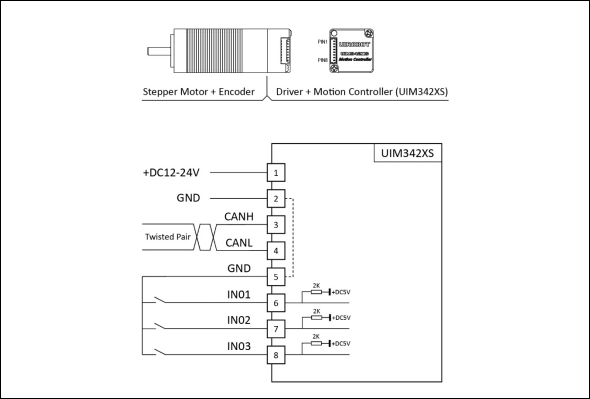
### UIM342XSA Wiring Diagram
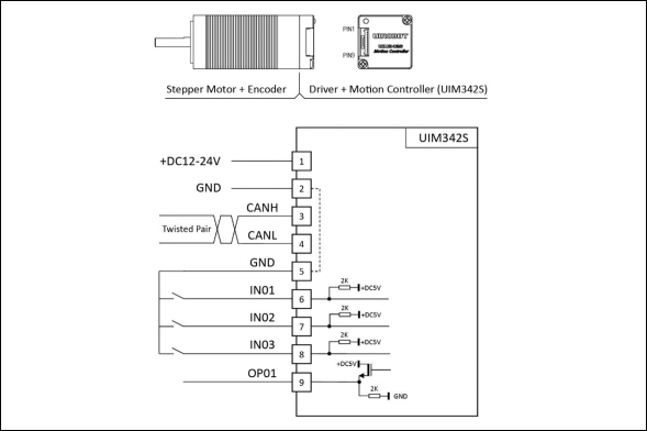
### UIM342SA Wiring Diagram
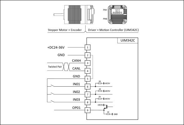
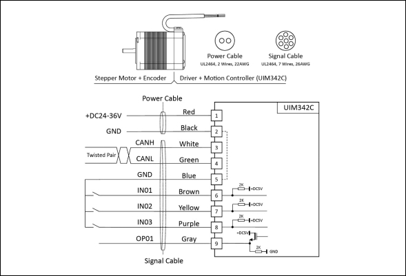
### UIM342A Wiring Diagram
The UIM342A is available in both socket-style and cable-style versions. Please refer to the wiring diagram included with your product package.
---
## Quick Start
This section explains how to quickly build and run a motor system consisting of 2 servo stepper motors equipped with UIM342A controllers and 1 UIM2513 gateway.
### Required Materials
- Windows PC
- UIM2513 Gateway (RS232-CAN converter)
- USB-232 Cable
- 2x UIM342A Servo Stepper Motors
- DC24V / 3A Minimum Power Supply
### Connection Steps
1. Connect power supply, CAN bus, and motors according to the wiring diagrams
2. **Double-check all wiring before powering on**
3. Connect UIM2513 gateway to PC
### Default Parameters
- UIM342A Initial ID: **5**
- UIM342A Initial Bitrate: **500K**
### Using StepEva3 Software
1. Download and run the Windows control panel **StepEva3**
2. Select **UIM2513 (RS232-CAN)** gateway
3. Select the UIM342A device to operate from the device list
4. Set motion parameters and control motor movement
### JOG Mode Operation
1. Select JOG Mode
2. Turn On Motor Driver
3. Type in desired Speed
4. Send Speed to UIM342A
5. Click to Start Motion
6. Stop Motion if needed
### PTP Mode Operation
1. Select PTP Mode
2. Turn On Motor Driver
3. Type in desired Speed
4. Type in desired Position
5. Send Settings to UIM342A
6. Click to Start Motion
7. Stop Motion if needed
---
## Connection Methods
UIM342A supports 4 ways to connect to user devices:
| Method | Description |
|--------|-------------|
| Direct CAN Bus | If user controller has a CAN port |
| UIM2513 Gateway | RS232-CAN converter (sold separately) |
| UIM2523 Gateway | Ethernet-CAN converter (sold separately) |
| UIC322(H) Adapter | USB-CAN adapter (sold separately) |
---
## Safety Precautions
### Precautions
| Precaution | Consequence of Neglect |
|------------|----------------------|
| Do not use in humid, corrosive, flammable gas environments or near flammable substances | Fire / Malfunction |
| Do not use the wire when soaked in oil/water | Fire / Malfunction |
| Do not touch the keyway with bare hands | Personal injury |
| Never touch the rotating parts of a running motor | Personal injury |
| Do not touch the running motor (may be very hot) | Personal injury |
| Do not frequently power on/off | Malfunction |
| Never modify, disassemble or repair by yourself | Fire / Malfunction / Personal injury |
| Power supply voltage must meet product requirements | Malfunction |
| Cut off power when not in use for long time | Fire / Malfunction / Personal injury |
### CAN Bus Precautions
> **WARNING**
- Avoid star connections. When CAN cable length exceeds 20 meters, dedicated CAN cables should be used. The length of branch cable to each node should not exceed 20 cm.
- UIM2513 has a built-in terminal resistor, which can be activated by the toggle switch. It is recommended to connect a 120-ohm terminal resistor to the other end of the CAN cable.
- **Strictly prohibit Hot-Plugging while power is on**. Hot-plugging may lead to ground loss, causing burnout of multiple UIM devices.
- Connect all UIM devices to a common ground.
---
## Downloads
- 📖 [UIM342A User Manual V6.03 (PDF)](https://www.uirobot.com/uploads/files/Manual_UIM342A%20V6.03.pdf)
- 📖 [StepEva3 User Manual V4.7 (PDF)](https://www.uirobot.com/uploads/files/Manual_StepEva3%20V4.7.pdf)
- 📖 [uirSDK3 User Manual V4.7 (PDF)](https://www.uirobot.com/uploads/files/f30fdec2ef52855e328edf9abcbd1d4e.pdf)
---
## Related Documents
- [CA Series Product Overview](/docs/ca-series)
- [UIM342 CAN Bus Smart Servo Stepper Motor Controller](/docs/uim342)
- [Quick Start Guide](/docs/quick-start)
- [UIM2513 CAN Bus Motion Control Gateway](/docs/uim2513)
- [UIM1616 CAN Bus IO Controller](/docs/uim1616)
- [Python CAN Bus Examples](/docs/python-examples)
- [Arduino CAN Bus Examples](/docs/arduino-examples)
---
*Last Updated: 2026-06-25 | Based on User Manual V6.03*