CAN Bus Motion Control Gateways
UIROBOT CAN bus motion control gateways — protocol conversion between CAN 2.0B, RS232, and Ethernet for seamless device networking.
UIROBOT motion control gateways bridge devices with different communication standards to a unified CAN bus network. Whether you need to connect legacy RS232 equipment (UIM2513), integrate Ethernet-based controllers (UIM2523), or prototype with Arduino (UI-MCP2515), there is a gateway for your application. All gateways support CAN 2.0B protocol and are designed for reliable operation in industrial environments.
---
## Product Lineup
| Model | Primary Interface | CAN Ports | Serial Ports | Ethernet | Isolation | Dimensions |
|-------|------------------|-----------|-------------|----------|-----------|------------|
| UIM2513 | RS232 | 2 x CAN 2.0B | RS232 | — | 2500V | 72 x 72 mm |
| UIM2523 | Ethernet | 1 x CAN 2.0B | — | RJ45 10/100M | 2500V | 72 x 72 mm |
| UI-MCP2515 | SPI (Arduino) | 1 x CAN 2.0A/B | — | — | — | PCB Module |
:::tip
Choose UIM2513 for RS232-to-CAN conversion, UIM2523 for network-to-CAN conversion, or UI-MCP2515 for Arduino prototyping.
:::
---
## UIM2513 — RS232 to CAN Gateway
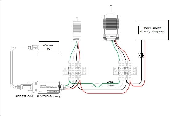
The UIM2513 is a multi-protocol motion control gateway with 2 independent CAN 2.0B channels and an RS232 serial interface. It performs bidirectional protocol conversion with a 1ms control cycle, making it ideal for connecting legacy serial devices to CAN bus motor networks.
### Key Features
:::grid{cols=2 style=card}
**Multi-Protocol Conversion**
Bidirectional CAN 2.0B <-> RS232. Supports transparent transmission and protocol parsing modes.
**Dual CAN Channels**
2 independent CAN 2.0B ports allow bridging two separate CAN networks or connecting CAN devices while maintaining a pass-through channel.
**High-Speed Processing**
1ms control cycle for protocol conversion and data forwarding. Motion control instructions are parsed and forwarded in real-time.
**2500V Isolation**
Galvanic isolation on CAN interfaces protects against ground loops and voltage spikes in industrial environments.
:::
### Specifications
| Parameter | Specification |
|-----------|--------------|
| Supply Voltage | 16–48 VDC |
| CAN Ports | 2 x CAN 2.0B |
| Serial Port | RS232 |
| CAN Baud Rate | 125K / 250K / 500K / 1M |
| Serial Baud Rate | 9600 / 19200 / 38400 / 57600 / 115200 |
| Max Node Count | 32+ per CAN channel |
| Isolation | 2500V (CAN) |
| Control Cycle | 1 ms |
| Dimensions | 72 x 72 mm |
| Mounting | DIN-rail / Screw |
| Operating Temp | -20 C to +70 C |
| Power Consumption | 3W max |
### Wiring Diagram
### RS232 Pinout
| Pin | Function | Connect To |
|-----|----------|-----------|
| TX | RS232 Transmit | Device RX |
| RX | RS232 Receive | Device TX |
| GND | Signal Ground | Device GND |
---
## UIM2523 — Ethernet to CAN Gateway
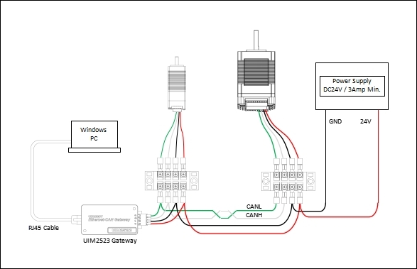
The UIM2523 bridges Ethernet TCP/IP networks to CAN 2.0B bus, enabling remote motion control and monitoring over standard network infrastructure.
### Key Features
:::grid{cols=2 style=card}
**Ethernet Connectivity**
10/100M Ethernet with RJ45 connector. Standard TCP/IP protocol support for easy integration with PCs, PLCs, and network controllers.
**Remote Access**
Control CAN bus motors from anywhere on the network. Ideal for distributed systems and remote monitoring applications.
**Multi-Device Networking**
Multiple UIM2523 gateways can be networked together, enabling centralized control of geographically distributed CAN bus segments.
**2500V Isolation**
Galvanic isolation on the CAN interface protects against industrial electrical noise.
:::
### Specifications
| Parameter | Specification |
|-----------|--------------|
| Supply Voltage | 16–48 VDC |
| CAN Ports | 1 x CAN 2.0B |
| Ethernet | 10/100M RJ45 |
| CAN Baud Rate | 125K / 250K / 500K / 1M |
| Protocol | TCP/IP, UDP |
| Max Node Count | 32+ per CAN channel |
| Isolation | 2500V (CAN) |
| Dimensions | 72 x 72 mm |
| Mounting | DIN-rail / Screw |
| Operating Temp | -20 C to +70 C |
### Wiring Diagram
---
## UI-MCP2515 — Arduino CAN Interface Module
The UI-MCP2515 is a compact SPI-to-CAN module based on the MCP2515 controller and TJA1050 transceiver. It plugs directly into Arduino development boards for rapid prototyping of CAN bus motor control systems.
### Key Features
:::grid{cols=2 style=card}
**Arduino Compatible**
Directly compatible with Arduino Uno, Mega, and other SPI-based development boards. No additional wiring required.
**CAN 2.0A/B Support**
Standard and extended frame formats. Baud rates from 125K to 1M.
**SPI Interface**
High-speed SPI communication with the host MCU. Does not occupy UART or I2C pins.
**Rapid Prototyping**
Ideal for proof-of-concept projects, educational use, and field debugging before deploying production gateways.
:::
### Specifications
| Parameter | Specification |
|-----------|--------------|
| CAN Controller | MCP2515 |
| CAN Transceiver | TJA1050 |
| Interface | SPI |
| CAN Protocol | CAN 2.0A / 2.0B |
| CAN Baud Rate | 125K / 250K / 500K / 1M |
| Operating Temp | -40 C to +85 C |
| Supply Voltage | 5V (from Arduino) |
### Arduino Wiring
```
+------------------+ +------------------+
| Arduino | | UI-MCP2515 |
+------------------+ +------------------+
| Pin 10 (CS) ---+---->| CS |
| Pin 11 (MOSI)---+---->| SI |
| Pin 12 (MISO)<--+-----| SO |
| Pin 13 (SCK) ---+---->| SCK |
| Pin 2 (INT) <--+-----| INT |
| 5V ---+---->| VCC |
| GND ---+---->| GND |
+------------------+ +------------------+
CAN Side:
+------------------+
| UI-MCP2515 |
+------------------+
| CANH --------->| CAN Bus High
| CANL --------->| CAN Bus Low
+------------------+
```
---
## System Architecture
### Gateway in a CAN Bus Network
```
+-------------------------------------------------------------------------+
| CONTROL SYSTEM |
| |
| +------------------+ +------------------+ |
| | PC / HMI | | PLC / MCU | |
| | (Ethernet or | | (RS232) | |
| | USB-CAN) | | | |
| +--------+---------+ +--------+---------+ |
| | | |
+-------------+-----------------------+------------------------------------+
| |
+--------v---------+ +--------v---------+
| UIM2523 | | UIM2513 |
| Ethernet -> CAN | | RS232 -> CAN |
+--------+---------+ +--------+---------+
| |
+-----------+-----------+
|
+-----------v-----------+
| CAN BUS |
| (ISO-11898, 1 Mbps) |
+--+------+------+-----+
| | |
+-----v-+ +--v---+ +v------+
|Motor 1| |Motor2| |Motor N|
|UIM342 | |UIM342| |UIM342 |
+-------+ +------+ +-------+
```
### Protocol Conversion Flow
| Source | Gateway | Destination | Use Case |
|--------|---------|-------------|----------|
| PC (RS232) | UIM2513 | CAN Bus Motors | Legacy PC control |
| PC (Ethernet) | UIM2523 | CAN Bus Motors | Networked control system |
| Arduino (SPI) | UI-MCP2515 | CAN Bus Motors | Prototyping and education |
---
## Quick Start
### Step 1 — Choose Your Gateway
| If you have... | Use... |
|----------------|--------|
| RS232 serial port on PC/PLC | UIM2513 |
| Ethernet network | UIM2523 |
| Arduino development board | UI-MCP2515 |
### Step 2 — Connect Hardware
1. Connect power supply (16–48 VDC for UIM2513/UIM2523, 5V USB for UI-MCP2515)
2. Wire CANH and CANL to the CAN bus (twisted pair recommended)
3. Connect your host device (RS232/Ethernet/SPI) to the gateway
### Step 3 — Configure
```bash
# Set gateway node ID (UIM2513)
geo gateway set-id --id 1 --port COM3
# Configure CAN baud rate
geo gateway config --baudrate 500000 --port COM3
# Verify connection
geo gateway status --port COM3
```
### Step 4 — Test
```bash
# Send a test command through the gateway
geo motor jog --id 1 --speed 500 --direction forward --port COM3
```
---
## Safety Precautions
### Electrical Safety
| Hazard | Precaution |
|--------|------------|
| High Voltage | Disconnect power before wiring. Use within specified voltage range only. |
| Short Circuit | Ensure proper wire gauge and insulation. Install a fuse on the power input line. |
| Grounding | Properly ground all devices to a common ground. Strictly prohibit hot-plugging while power is on. |
### Operational Safety
| Hazard | Precaution |
|--------|------------|
| Overheating | Ensure adequate ventilation. Operating temperature: -20°C to +70°C. |
| ESD | Use anti-static precautions when handling. Discharge static before touching terminals. |
| Mounting | Secure the device firmly. Do not operate with loose mounting. |
### CAN Bus Safety
| Hazard | Precaution |
|--------|------------|
| Termination | Install 120Ω termination resistors at both ends of the CAN bus. |
| Hot-Plugging | Strictly prohibit hot-plugging while power is on. May cause device burnout. |
| Cable Length | Use twisted pair cable. Keep branch lines under 20 cm for long-distance runs. |
## Applications
:::grid{cols=3 style=card}
**Legacy Device Integration**
Connect RS232 equipment to modern CAN bus motor networks without replacing existing hardware.
**Networked Motion Control**
Control distributed CAN bus motors over Ethernet from a central PC or PLC.
**Rapid Prototyping**
Quickly build and test CAN bus motor control systems with Arduino before committing to production hardware.
:::
---
## Related Products
| Product | Description |
|---------|-------------|
| UIM342 | CAN bus smart motor controller |
| UIC320A | USB to CAN 2.0B adapter (isolated) |
| UIM0808 | 8-ch digital I/O CAN bus module |
| UIM1616 | 16-ch digital I/O CAN bus module |
| MMC90X | Miniature motion control computer |
---
## Resources
:::tip
Download datasheets, user manuals, and sample code from the [UIROBOT Download Center](https://www.uirobot.com/serve/list-437.html).
:::
- **UIM2513 Datasheet** — PDF
- **UIM2523 Datasheet** — PDF
- **UI-MCP2515 Datasheet** — PDF
- **Arduino Examples** — MCP2515 driver, motor control
- **Python Examples** — python-can integration
---
*Last Updated: 2026-06-25*