UIM2513 CAN Bus Motion Control Gateway
The UIM2513 CAN Bus Motion Control Gateway integrates multi-protocol conversion and motion control coordination. It supports bidirectional data conversion between CAN 2.0B, RS232, and RS485, enabling devices with different communication standards to connect seamlessly to a unified CAN bus network. Ideal for device networking and system integration in complex motion control systems.
# UIM2513 Industrial RS232-CAN Gateway — Technical Reference
> RS232 to CAN bus gateway for connecting UIROBOT servo stepper motors, motion controllers, and I/O controllers
---
## Product Overview
The UIM2513 is an industrial serial port (RS232 protocol) to CAN gateway, designed for UIROBOT's Integrated Servo Stepper Motors and Control System. Users can send instructions through UIM2513 to control UIM series servo stepper, AC servo motion controller and I/O controller products.
### Key Features
:::grid{cols=2 style=card}
**- **Control System**: Robust DSP hardware, fault tolerance, fail-safe user interface**
- **RS232 Serial Communication**: DB9 Female interface, 1500V photoelectric isolation
**- **CAN Networking**: Active CAN 2.0, 1 Mbps max, 1500V photoelectric isolation**
- **SDK**: Complete SDK, DLL, LIB, SO files with C++ and C# sample codes
**- **Wide Voltage Input**: 12~48VDC**
$6
:::
- **Compact Design**: Aluminum alloy casing, sturdy and durable for easy heat dissipation
---
## Technical Specifications
### Absolute Maximum Ratings
| Parameter | Specification |
|-----------|---------------|
| Ambient temperature under bias | -40°C ~ 85°C |
| Storage temperature | -65°C ~ +150°C |
| Voltage on V+ with respect to V- | -0.3V ~ 50V |
### Operating Conditions (at ambient temperature 25°C)
| Parameter | Min | Max | Unit |
|-----------|-----|-----|------|
| Supply voltage (DC) | 12 | 48 | V |
| Input Current | 0 | 100 | mA |
### Operating Environment
| Parameter | Specification |
|-----------|---------------|
| Cooling | Free Air |
| Environment | Avoid dust, oil mist and corrosive gases |
| Operating temperature | -40°C ~ 85°C |
| Humidity | < 80% RH, no condensation, no frost |
| Vibration | 3G Max |
| Storage | -65°C ~ 150°C |
### Communication Interface
| Parameter | Specification |
|-----------|---------------|
| CAN Protocol | Active CAN 2.0 |
| CAN Physical | 2 wires, CANH, CANL, twisted pair |
| CAN Driver | Max. 1 Mbps |
| CAN Standard | Meets ISO-11898 standard physical layer requirements |
| CAN Isolation | 1500V isolated, differential bus |
| RS232 Physical | 3 wires, DB9 Female Connector |
### Mechanical Parameters
| Parameter | Specification |
|-----------|---------------|
| Dimensions | 74 × 38 × 14 mm |
| Weight | 0.15 Kg |
---
## Hardware
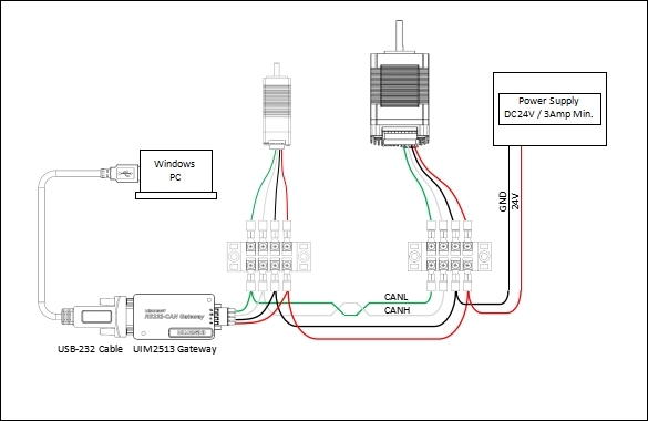
### Wiring Diagram
### Pin Description
| Pin | Function | Color | Description |
|-----|----------|-------|-------------|
| V+ | Supply voltage positive | Red | 12–48 VDC |
| V- | Supply voltage negative | Black | 0 V |
| CH | CANH | White | CAN Bus High |
| CL | CANL | Green | CAN Bus Low |
| DB9 Pin 2 | Data to Host | - | RS232 RX |
| DB9 Pin 3 | Data from Host | - | RS232 TX |
| DB9 Pin 5 | GND | - | Signal Ground |
---
## CAN Network & ID Configuration
The UIM2513 uses Active CAN 2.0B hardware and software, with CAN bit rate configurable from 125K to 1000Kbps via instructions.
### CAN ID Types
| ID Type | Description |
|---------|-------------|
| **Node ID** | Configurable via instructions (UIM2513 fixed = 3) |
| **Group ID** | Configurable via instructions, for group synchronization |
| **Global ID** | Fixed as 0, all devices respond |
---
## Protocol
### UIMessage Frame Structure
UIM2513 and the user controller exchange information using UIMessages. The length of a UIMessage is fixed to 16 bytes.
```
┌─────┬─────┬─────┬─────┬─────┬─────┬─────┬─────┬─────┬─────┬─────┐
│ SM │ ID │ CW │ d0 │ ... │ d7 │ d8 │ R0 │ R1 │ CC │ │
│ AA │ │ │ │ │ │ Aux │ │ │ EM │ │
└─────┴─────┴─────┴─────┴─────┴─────┴─────┴─────┴─────┴─────┴─────┘
```
- **SM**: Start of Message (0xAA with CRC, 0xAD without CRC)
- **ID**: Device ID (1 byte)
- **CW**: Control Word (1 byte, bit7: 0=No ACK, 1=Need ACK)
- **DL**: Data Length (1 byte)
- **d0-d7**: Data bytes (low byte first)
- **R1:R0**: RTU CRC16
- **EM**: End of Message (fixed 0xCC)
---
## Instruction Set
### PP[i] Protocol Parameter
| Mnemonic | Control Word | Function | Description |
|----------|--------------|----------|-------------|
| `PP[i]` | 0x01 | Set/Get | Protocol Parameters |
| i | Description | Value (N) |
|---|-------------|-----------|
| 1 | RS232 baud rate (bps) | 0: 4.8K, 1: 9.6K, 2: 19.2K, 3: 38.4K, 4: 57.6K, 5: 115.2K |
| 5 | CAN bit rate (bps) | 0: 1000K, 1: 800K, 2: 500K, 3: 250K, 4: 125K |
| 7 | Node ID | UIM2513 ID fixed = 3 |
### ML Model Information
| Mnemonic | Control Word | Function | Description |
|----------|--------------|----------|-------------|
| `ML` | 0x0B | Get | Model, function module and firmware version |
### SN Serial Number
| Mnemonic | Control Word | Function | Description |
|----------|--------------|----------|-------------|
| `SN` | 0x0C | Get | Serial number of the device |
### ER[i] Error Report
| Mnemonic | Control Word | Function | Description |
|----------|--------------|----------|-------------|
| `ER[i]` | 0x0F | Clear/Get | Error Report |
| i | Description |
|---|-------------|
| 0 | Get/Clear the latest error content |
| 6 | Get/Clear power on error |
| 10 | Get/Clear latest errors |
| 11…18 | Get/Clear the last 2…9 errors |
### SY[i] System Operation
| Mnemonic | Control Word | Function | Description |
|----------|--------------|----------|-------------|
| `SY[i]` | 0x7E | Set | System Operation |
| i | Description |
|---|-------------|
| 1 | Reboot the device |
| 2 | Restore factory defaults |
---
## Quick Start
This section explains how to quickly build and run a motor system consisting of 2 servo stepper motors equipped with UIM342 controllers and 1 UIM2513 gateway.
### Required Materials
- Windows PC
- UIM2513 Gateway
- USB-232 Cable
- 2x UIM342 Servo Stepper Motors
- DC24V / 3A Minimum Power Supply
### Connection Steps
1. Wire the system as shown in the wiring diagram
2. **Double-check all wiring before powering on**
3. Connect UIM2513 gateway to PC via USB-232 cable
### Default Parameters
- UIM2513 Node ID: **3** (fixed)
- UIM342 Initial ID: **5**
- UIM342 Initial Bitrate: **500K**
### Using StepEva3 Software
1. Download and run the Windows control panel **StepEva3**
2. Select **UIM2513 (RS232-CAN)** gateway
3. Select the device to operate from the device list
4. Refer to the corresponding User Manual of the selected device to operate
---
## CAN Bus Precautions
:::warning
**WARNING**
- Avoid star connections. When CAN cable length exceeds 20 meters, dedicated CAN cables should be used. The length of branch cable to each node should not exceed 20 cm.
- UIM2513 has a built-in terminal resistor, which can be activated by the toggle switch. It is recommended to connect a 120-ohm terminal resistor to the other end of the CAN cable.
- **Strictly avoid hot-plugging while power is on**. Hot-plugging may lead to ground loss, causing burnout of multiple UIM devices.
- Connect all UIM devices to a common ground.
---
## Safety Precautions
| Precaution | Consequence of Neglect |
|------------|----------------------|
| Do not use in humid, corrosive, flammable gas environments or near flammable substances | Fire / Malfunction |
| Do not use the wire when soaked in oil/water | Fire / Malfunction |
| Do not frequently power on/off | Malfunction |
| Never modify, disassemble or repair by yourself | Fire / Malfunction |
| Power supply voltage must meet product requirements | Malfunction |
| Cut off power when not in use for long time | Fire / Malfunction |
---
:::
---
## Video Tutorial
:::video[Installation for UIM25I3 RS232-CAN Gateway Compatible L-com Line Driver](https://www.youtube.com/watch?v=I9da-Qr2hR8)
:::
:::video[Can we achieve fast control of the motor using a USB-CAN gateway?](https://www.youtube.com/watch?v=B2tyNLocnoI)
:::
---
## Downloads
- 📖 [UIM2513 User Manual V5.9 (PDF)](https://www.uirobot.com/uploads/files/Manual_UIM2513%20V5.9.pdf)
- 📖 [StepEva3 User Manual V4.7 (PDF)](https://www.uirobot.com/uploads/files/Manual_StepEva3%20V4.7.pdf)
- 📖 [uirSDK3 User Manual V4.7 (PDF)](https://www.uirobot.com/uploads/files/f30fdec2ef52855e328edf9abcbd1d4e.pdf)
---
## Related Documents
- [UIM342 CAN Bus Smart Servo Stepper Motor Controller](/docs/uim342)
- [UIM342A CAN Bus Smart Servo Stepper Motor Controller](/docs/uim342a)
- [UIM1616 Digital I/O Controller — Technical Reference](/docs/uim1616)
- [CAN Bus Compact I/O Modules — Quick Overview](/docs/compact-io-module)
- [Quick Start Guide](/docs/quick-start)
---
*Last Updated: 2026-06-23 | Based on User Manual V5.9*