UIM1616 & UIM0808 CAN Bus I/O Module
The UIM1616 CAN Bus I/O Controller supports 16 digital inputs and 16 digital outputs, integrating the CAN 2.0B communication protocol. It is designed for remote I/O expansion and distributed control in industrial automation systems.
# UIM1616 & UIM0808 Digital I/O Module — Technical Reference
> Complete technical specifications, instruction set, and wiring guide for UIM0808/UIM1616 CAN bus I/O controllers
---
## Product Overview
The UIM1616 is a Digital I/O Controller with CAN Bus communication interface. Users can communicate with the UIM1616 through UIM Gateways (e.g. RS232 / USB / Ethernet) or through user CAN devices. The UIM1616 embeds a high-performance DSP processing system with simple instruction set and high fault tolerance.
### Key Features
:::grid{cols=2 style=card}
**Control System**
Robust DSP hardware, fault tolerance, digital filter, input change notification.
**Input Ports**
Up to 16 digital inputs with 1500V photoelectric isolation and ESD protection.
**Output Ports**
Up to 16 digital outputs with 1500V isolation, overheat/overload protection.
**CAN Networking**
Active CAN 2.0, 1 Mbps max, 1500V isolated. SDK with C++/C# samples.
:::
---
## Product Models
| Parameter | UIM1616 | UIM0808 |
|-----------|---------|---------|
| **Supply Voltage** | 12-24 VDC | 12-24 VDC |
| **Digital Inputs** | 16 channels | 8 channels |
| **Digital Outputs** | 16 channels | 8 channels |
| **Output Current per Port** | 500 mA | 500 mA |
| **Max Total Output Current** | 4000 mA | 4000 mA |
| **Dimensions** | 120 × 68 × 12 mm | 78 × 68 × 12 mm |
### Order Code Structure
```
UIM [I/O Quantity] [User Code]
I/O Quantity:
1616 = 16 Inputs / 16 Outputs
0808 = 8 Inputs / 8 Outputs
```
---
## Core Functions
### Control System
- Robust DSP hardware platform
- Fault tolerance, fail-safe user interface
- Digital filter for noise immunity
- Input change notification
- Complete SDK, LIB and DLL provided
- C++ and C# sample codes
### Input Ports
- Up to 16 digital input ports
- 1 quadrature encoder interface
- 1500V photoelectric isolation
- ESD protection
### Output Ports
- Up to 16 digital output ports
- 500 mA output current per port
- 1500V photoelectric isolation
- ESD protection
- Overheat protection
- Overload protection
- Short circuit protection
- Overvoltage protection
- Current limiting
### CAN Networking
- Active CAN 2.0, 1 Mbps max
- 1500V photoelectric isolation
- Support 3 types of IDs:
- Node ID
- Group ID
- Global ID
### Other Features
- Compact structure, easy to install and use
- Simple mechanical/electrical interface
- Small size: 120 × 68 × 12 mm (UIM1616) / 78 × 68 × 12 mm (UIM0808)
---
## Technical Specifications
### Absolute Maximum Ratings
| Parameter | Specification |
|-----------|---------------|
| Ambient temperature under bias | -40°C ~ 85°C |
| Storage temperature | -65°C ~ +150°C |
| Voltage on V+ with respect to V- | -0.3V ~ 36V |
| Voltage on input ports with respect to V- | -0.3V ~ 40V |
| Voltage on output ports with respect to V- | -0.3V ~ 40V |
| Maximum current sunk by any output port | 1000 mA |
| Maximum current sunk by all output ports | 4000 mA |
### Operating Conditions (at ambient temperature 25°C)
| Parameter | Min | Max | Unit |
|-----------|-----|-----|------|
| Supply voltage (DC) | 12 | 24 | V |
| Current Output / port | 0 | 500 | mA |
| Voltage on input ports | 0 | 24 | V |
### Operating Environment
| Parameter | Specification |
|-----------|---------------|
| Cooling | Free Air |
| Environment | Avoid dust, oil mist and corrosive gases |
| Operating temperature | -40°C ~ 85°C |
| Humidity | < 80% RH, no condensation, no frost |
| Vibration | 3G Max |
| Storage | -65°C ~ 150°C |
### Communication Interface
| Parameter | Specification |
|-----------|---------------|
| Protocol | Active CAN 2.0 |
| Physical Layer | Two-wire system, CANH, CANL, twisted pair |
| CAN Driver | Max. 1 Mbps |
| Standard | Meets ISO-11898 standard physical layer requirements |
| Isolation | 1500V isolated, differential bus |
---
## Wiring Diagrams
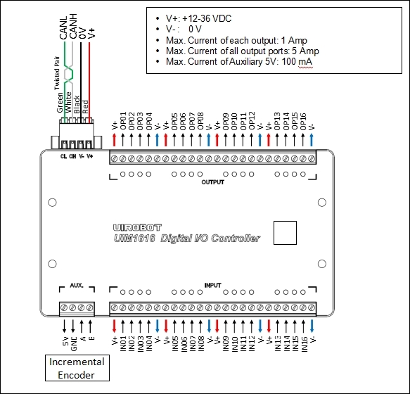
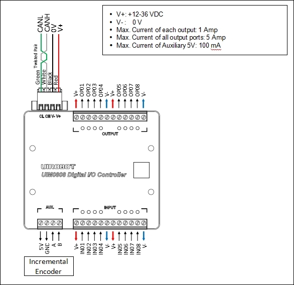
### UIM1616 Wiring
### Input Wiring (NPN Sensor)
### Output Wiring (Inductive Load)
```
UIM1616
┌─────┐
V+ ──────┤ ├──── Load +
│ OPx │
V- ──────┤ ├──── Load -
└─────┘
Note: Install flyback diode in the direction shown for inductive loads.
```
---
:::tip
UIM1616 supports 16 digital inputs and 16 digital outputs with 1500V isolation. Each input features continuous, low-pass filtered, and single-trigger modes with change-of-state notification.
:::
## I/O Configuration
### Digital Input
- 16 channels, NPN type
- Input voltage: 0-24VDC
- Optocoupler isolation (1500V)
- Configurable trigger mode per input:
- **Continuous trigger** (TG[i]=0)
- **Filtered trigger** (TG[i]=1~60000 ms low-pass filter)
### Digital Output
- 16 channels, MOSFET push-pull
- Output current: 500 mA per channel
- Max total current: 4000 mA
- Protection: overheat, overload, short circuit, overvoltage
### Auxiliary Encoder
- 1 quadrature encoder interface (A/B phase)
- 5V supply for encoder
- Configurable counting period via QE[0]
- Features:
- **SP**: Get encoder speed (count increment per second)
- **PR**: Get encoder periodical count increment
- **PA**: Get encoder total count
- **OG**: Clear encoder counter
---
## Instruction Set Summary
### Protocol Instructions
| Mnemonic | Control Word | Function | Description |
|----------|--------------|----------|-------------|
| `PP[i]` | 0x01 | Set/Get | Protocol Parameters |
### System Instructions
| Mnemonic | Control Word | Function | Description |
|----------|--------------|----------|-------------|
| `IE[i]` | 0x07 | Set/Get | Information Enable |
| `ML` | 0x0B | Get | Model Information |
| `SN` | 0x0C | Get | Serial Number |
| `ER[i]` | 0x0F | Clear/Get | Error Report |
| `QE[i]` | 0x3D | Set/Get | Quadrature Encoder |
| `SY[i]` | 0x7E | Set | System Operation (Reboot/Factory Reset) |
### I/O Instructions
| Mnemonic | Control Word | Function | Description |
|----------|--------------|----------|-------------|
| `TG[i]` | 0x35 | Set/Get | Input Trigger Type |
| `DI` | 0x37 | Set/Get | Digital Input/Output |
### Auxiliary Encoder Instructions
| Mnemonic | Control Word | Function | Description |
|----------|--------------|----------|-------------|
| `SP` | 0x1E | Get | Encoder Speed |
| `PR` | 0x1F | Get | Encoder Periodical Counts |
| `PA` | 0x20 | Get | Encoder Counts |
| `OG` | 0x21 | Set | Clear Encoder Counter |
### Notification Instructions
| Mnemonic | Control Word | Function | Description |
|----------|--------------|----------|-------------|
| `RT` | 0x5A | Auto Sent | Real-Time Information |
---
## Quick Start
This section explains how to quickly set up and run a system composed of a UIM1616 and a UIM2513 Gateway.
### Required Materials
- Windows PC
- UIM2513 Gateway (RS232-CAN converter)
- USB-232 Cable
- UIM1616 I/O Controller
- DC24V / 3A Minimum Power Supply
### Connection Steps
1. Wire the system as shown in the wiring diagram
2. **Double-check all wiring before powering on**
3. Connect UIM2513 gateway to PC
### Default Parameters
- UIM1616 Initial ID: **7**
- UIM1616 Initial Bitrate: **500K**
### Using StepEva3 Software
1. Download and run the Windows control panel **StepEva3**
2. Select **UIM2513 (RS232-CAN)** gateway
3. Select the UIM1616 device to operate from the device list
4. Use the I/O control panel to read inputs and control outputs
---
## CAN Bus Precautions
> **WARNING**
- Avoid star connections. When CAN cable length exceeds 20 meters, dedicated CAN cables should be used. The length of branch cable to each node should not exceed 20 cm.
- UIM2513 has a built-in terminal resistor, which can be activated by the toggle switch. It is recommended to connect a 120-ohm terminal resistor to the other end of the CAN cable.
- **Strictly avoid hot-plugging while power is on**. Hot-plugging may lead to ground loss, causing burnout of multiple UIM devices.
- Connect all UIM devices to a common ground.
---
## Safety Precautions
| Precaution | Consequence of Neglect |
|------------|----------------------|
| Do not use in humid, corrosive, flammable gas environments or near flammable substances | Fire / Malfunction |
| Do not use the wire when soaked in oil/water | Fire / Malfunction |
| Do not frequently power on/off | Malfunction |
| Never modify, disassemble or repair by yourself | Fire / Malfunction |
| Power supply voltage must meet product requirements | Malfunction |
| Cut off power when not in use for long time | Fire / Malfunction |
---
## Video Tutorial
:::video[In what applications are servo stepper motors commonly used?](https://www.youtube.com/watch?v=BKWmdWwrXGw)
:::
:::video[UIROBOT Control System Modules - Simple, Robust, Compact.](https://www.youtube.com/watch?v=DVb7QDI8uFo)
:::
---
## Downloads
- 📖 [UIM1616 User Manual V4.7 (PDF)](https://www.uirobot.com/uploads/files/Manual_UIM1616%20V4.7.pdf)
- 📖 [StepEva3 User Manual V4.7 (PDF)](https://www.uirobot.com/uploads/files/Manual_StepEva3%20V4.7.pdf)
- 📖 [uirSDK3 User Manual V4.7 (PDF)](https://www.uirobot.com/uploads/files/f30fdec2ef52855e328edf9abcbd1d4e.pdf)
---
## Related Documents
- [CAN Bus Compact I/O Modules](/docs/compact-io-module) - Product lineup overview for UIM0808/UIM1616
- [UIM342 CAN Bus Smart Servo Stepper Motor Controller](/docs/uim342)
- [UIM342A CAN Bus Smart Servo Stepper Motor Controller](/docs/uim342a)
- [UIM2513 CAN Bus Motion Control Gateway](/docs/uim2513)
- [Quick Start Guide](/docs/quick-start)
---
*Last Updated: 2026-06-23 | Based on User Manual V4.7*