UIC322H USB-CAN High-Speed Isolated Protocol Converter
5000VDC Fully Isolated USB to CAN Adapter with Industrial-Grade Design. Supports CAN2.0A/B, USB 2.0, ±15kV ESD protection.
> 5000VDC Full Isolated Universal USB to CAN Adapter with Industrial-Grade Design
---
## Product Overview
The UIC322H is a high-performance USB-to-CAN adapter designed for industrial environments. Based on the Silicon Labs CP2102N USB-to-serial controller, it offers broad operating system compatibility including Windows, Linux (kernel 3.0.0-19 and later), macOS, and Android.
The adapter provides **5000 VDC isolation** between the USB and CAN Bus for both power and data, supporting USB virtual COM port baud rates up to 2 Mbps and CAN Bus bit rates up to 1 Mbps. TX and RX lines feature enhanced ESD protection of **±8 kV (contact)** and **±15 kV (air)**, helping protect both the host USB port and connected CAN devices from voltage spikes, static discharge, and transient surges.
::: tip Key Advantages
- **5000 VDC full isolation** for both power and signal
- **USB powered**, USB 2.0 compliant, full-speed (12 Mbps)
- Supports **CAN2.0A** (standard frame) and **CAN2.0B** (extended frame)
- Industrial-grade design with rugged cast metal enclosure
:::
---
## Features
:::grid{cols=2 style=card}
**Isolation & Protection**
- 5000 VDC full isolation (power + signal)
- ESD protection: ±8 kV (contact), ±15 kV (air)
- IEC 61000-4-2 Level 4 compliant
**CAN Interface**
- CAN2.0A / CAN2.0B support
- Bit rates: 50k ~ 1000k bps
- ISO 11898 compliant
:::
:::grid{cols=2 style=card}
**USB Interface**
- USB 2.0 full-speed (12 Mbps)
- Virtual COM port: 9,600 ~ 2,000,000 bps
- Plug & Play, no external power needed
**Operating Modes**
- Normal Mode
- Loopback Mode (internal test)
- Listen-Only Mode
:::
---
## Block Diagram
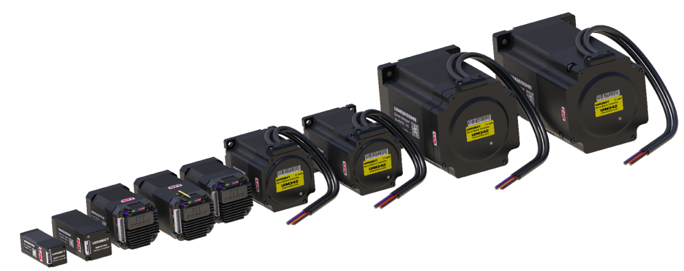
*Figure: UIC322H internal functional architecture — USB to CAN with 5000VDC isolation*
---
## Product Model
The UIC322H is a standalone USB-to-CAN adapter. It is part of the UIROBOT protocol converter family.
| Model | Interface | CAN Channels | Isolation | ESD Protection | Host Connection |
|-------|-----------|-------------|-----------|---------------|-----------------|
| **UIC322H** | USB 2.0 (Virtual COM) | 1 x CAN 2.0B | 5000 VDC | ±15 kV (air) | USB Type-A |
| UIC321H | RS232 | 1 x CAN 2.0B | 2500 VDC | — | DB9 / Terminal |
| UIC324H | RS485 | 1 x CAN 2.0B | 2500 VDC | — | Terminal |
---
## Specifications
### General Information
| Parameter | Specification |
|-----------|---------------|
| Part Number | UIC322H |
| Host OS Support | Windows (32/64-bit), Linux (kernel 3.0.0-19+), MacOS 8+, Android |
| USB Interface | Type A, Cast Aluminum Alloy, USB1.1/2.0 |
| Power | From USB port (no external power required) |
### Isolation & Protection
| Parameter | Specification |
|-----------|---------------|
| USB / CAN Isolation | 5000 VDC |
| ESD Protection (TX/RX) | ±8 kV (contact) |
| IEC 61000-4-2 (Direct discharge) | 15 kV (Level 4) |
| IEC 61000-4-2 (Air discharge) | 15 kV (Level 4) |
| MIL-STD-883, Method 3015.7 | 15 kV |
::: warning Important
The 5000 VDC isolation protects both the host computer and CAN bus devices from ground loops and voltage transients. Always ensure proper grounding for optimal performance.
:::
### CAN Interface
| Parameter | Specification |
|-----------|---------------|
| Connector | Flip-clip paired connector, 2×2 pin |
| Signals | Isolated CANH, CANL, CGND (optional) |
| Bit Rates | 50k, 125k, 250k, 500k, 800k, 1000k bps |
| Physical Layer | Compliant with ISO 11898 |
### USB Virtual COM Parameters
| Parameter | Specification |
|-----------|---------------|
| Data Bits | 8 (fixed) |
| Stop Bits | 1 (fixed) |
| Parity | None (fixed) |
| Supported Baud Rates | 9,600 / 14,400 / 16,000 / 19,200 / 28,800 / 38,400 / 51,200 / 56,000 / 57,600 / 64,000 / 76,800 / 115,200 / 128,000 / 153,600 / 230,400 / 250,000 / 256,000 / 460,800 / 500,000 / 576,000 / 921,600 / 1,000,000 / 1,200,000 / 1,500,000 / 2,000,000 bps |
### Mechanical & Environmental
| Parameter | Specification |
|-----------|---------------|
| Enclosure | Aluminum |
| Cable Length | 1 ft. (30 cm) |
| Weight | 50 g |
| Operating Temperature | -40°C to +85°C |
| Operating Humidity | 5% to 85% RH |
| Warranty | 1-year limited warranty |
---
## Wiring
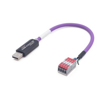
*Figure: UIC322H wiring — White (CANH), Green (CANL), Black (CGND)*
### Wire Color Code
| Color | Signal | Description |
|-------|--------|-------------|
| White | CH | CAN High |
| Green | CL | CAN Low |
| Black | CGND | CAN Ground |
### Terminal Resistor
::: tip
The UIC322H includes a built-in 120Ω terminal resistor that can be enabled via software configuration. For networks with multiple nodes, enable the terminal resistor at both ends of the CAN bus.
:::
---
## Quick Start
### Communication Architecture
```mermaid
graph LR
A[Host PC] -->|USB| B[UIC322H]
B -->|CAN Bus| C[CAN Devices]
subgraph "UIC322H Internal"
D[CP2102N USB Chip] --> E[UART]
E --> F[DSP]
F --> G[Digital Isolator]
G --> H[CAN Driver]
end
```
### Initialization Steps
1. **Configure Serial Port**
- Data bits: 8
- Stop bits: 1
- Parity: None
- Select one of the supported baud rates
2. **Initialize UART Baud Rate**
::: warning Critical Step
After opening the COM port, send a single byte `0x55` to the UIC322H. This command sets the UART baud rate on the UIC322H side to match the host.
:::
3. **Initialize CAN Controller**
- Send a **CAN-CFG Frame** to configure the internal CAN controller
- Set CAN bit rate (50k / 125k / 250k / 500k / 800k / 1000k bps)
- Set operating mode (Normal / Loopback / Listen Only)
4. **Sending / Receiving CAN Messages**
- To transmit: Send a **CAN-TXM Frame** to the UIC322H
- To receive: UIC322H sends **CAN-RXM Frame** when CAN message received
5. **Error Handling**
- If an error occurs, UIC322H sends an **ERR-MSG Frame** to the host
### Serial Port Debugging Example
Below is an example of using a serial port debugging tool to initialize and communicate with the UIC322H:

*Figure: Serial port debug tool — Init UART (0x55), send CAN-CFG/TXM Frame, receive CAN-RXM/ERR-MSG Frame*
### Communication Flow
*Figure: UIC322H communication flow — Host ↔ UIC322H ↔ CAN Bus*
```mermaid
sequenceDiagram
participant H as Host
participant U as UIC322H
participant C as CAN Bus
H->>U: 0x55 (Init UART)
U->>H: ACK
H->>U: CAN-CFG Frame
U->>H: ACK (if required)
loop Data Exchange
H->>U: CAN-TXM Frame
U->>C: CAN Message
C->>U: CAN Message
U->>H: CAN-RXM Frame
end
```
---
## UART Protocol
### UART Message Frame Structure
All communication uses fixed-length (**18 Bytes**) UART frames:
| Byte | 0 | 1 | 2-16 | 17-18 | 19 |
|------|---|---|------|-------|----|
| Name | AA | CW | Payload | CRC | CC |
::: note Frame Fields
- **AA**: Frame header, normally 0xAA (use 0xAD if CRC not required)
- **CW**: UART Message Control Word
- **Payload**: 15 bytes, content depends on command type
- **CRC**: CRC-16/MODBUS (see Appendix 1)
- **CC**: Frame ending marker, always 0xCC
:::
::: tip Endianness
All multi-byte numeric fields are transmitted in **little-endian** format.
- Example: 0x87654321 → send 0x21, 0x43, 0x65, 0x87
:::
### CAN-CFG Frame (Configuration)
The Host must send a CAN-CFG Frame during initialization:
| Byte | 0 | 1 | 2 | 3-4 | 5-6 | 7-10 | 11-14 | 15-16 | 17 |
|------|---|---|---|-----|-----|------|-------|-------|----|
| Name | AA | CW | CFG | 00 | BR0-BR1 | FT0-FT3 | MK0-MK3 | CRC | CC |
#### Configuration Fields
| Field | Bytes | Description |
|-------|-------|-------------|
| CW | 1 | 0x01 or 0x81 (require ACK) |
| CFG | 1 | EID: 0=Standard ID (11-bit), 1=Extended ID (29-bit) |
| BR1:BR0 | 2 | CAN Bit-Rate: 50, 125, 250, 500, 800, 1000 (Kbps) |
| FT3:FT0 | 4 | CAN message filter |
| MK3:MK0 | 4 | CAN message filter mask |
#### Operating Modes
| MD1 | MD0 | Mode | Description |
|-----|-----|------|-------------|
| 0 | 0 | Normal | Standard operation |
| 0 | 1 | Loopback | Internal test mode |
| 1 | 0 | Listen-Only | Receive without transmitting |
| 1 | 1 | Monitor-All | Receive all messages (including errors) |
### CAN-TXM Frame (Transmit)
| Byte | 0 | 1 | 2-5 | 6 | 7-14 | 15-16 | 17 |
|------|---|---|-----|---|------|-------|----|
| Name | AA | CW | ID0-ID3 | DLC | B0-B7 | CRC | CC |
| Field | Bytes | Description |
|-------|-------|-------------|
| CW | 1 | 0x03 or 0x83 (require ACK) |
| ID3:ID0 | 4 | CAN ID (32 bits) |
| DLC | 1 | Data Length Control Byte |
| LEN | - | Number of valid data bytes |
| RTR | - | 0=Normal message, 1=Remote Transmission Request |
| IDE | - | 0=Standard CAN ID (11-bit), 1=Extended CAN ID (29-bit) |
| B0-B7 | 8 | CAN Message Data Bytes |
### CAN-RXM Frame (Receive)
| Byte | 0 | 1 | 2-5 | 6 | 7-14 | 15-16 | 17 |
|------|---|---|-----|---|------|-------|----|
| Name | AA | CW | ID0-ID3 | DLC | B0-B7 | CRC | CC |
| Field | Bytes | Description |
|-------|-------|-------------|
| CW | 1 | 0xD0 |
| ID3:ID0 | 4 | CAN ID (32 bits) |
| DLC | 1 | Data Length Control Byte |
| LEN | - | Number of valid data bytes |
| RTR | - | 0=Normal message, 1=Remote Transmission Message |
| IDE | - | 0=Standard CAN ID (11-bit), 1=Extended CAN ID (29-bit) |
| B0-B7 | 8 | CAN Message Data Bytes |
---
## Error Messages
When an error occurs, UIC322H sends error frames to the host:
### Error Codes
| Code | Hex | Error Type | Description |
|------|-----|------------|-------------|
| 0x00 | F0 00 | CAN Not Initialized | CAN-TXM received before CAN-CFG |
| 0x01 | F0 01 | Unknown CW | Unrecognized Control Word |
| 0x02 | F0 02 | CRC Failure | CRC integrity check failed |
| 0x03 | F0 03 | Invalid Bit Rate | Unsupported CAN bit rate |
| 0x10 | F1 00 | Frame Too Short | UART frame < 18 bytes |
| 0x11 | F1 01 | CAN TX/RX Error | CAN transmit/receive error |
### Error Frame Format
```
AA F0 [Error Code] [Data...] [CRC0] [CRC1] CC
```
::: danger Important
If you receive Error Code 0x00, ensure you have sent the CAN-CFG Frame before attempting to transmit CAN messages.
:::
---
## Get Device Information
To retrieve device information such as the serial number:
**Request (Host → UIC322H):**
```hex
AA 00 00 00 00 00 00 00 00 00 00 00 00 00 00 AB 01 CC
```
or (without CRC):
```hex
AD 00 00 00 00 00 00 00 00 00 00 00 00 00 00 00 00 CC
```
**Response (UIC322H → Host):**
```hex
AA 00 SN0 SN1 SN2 SN3 00 00 00 00 00 00 00 00 00 CRC0 CRC1 CC
```
Where SN3:SN2:SN1:SN0 is the device serial number (32-bit).
::: tip Example
Response: `AA 00 01 02 03 04 00 00 00 00 00 00 00 00 00 1E D6 CC`
Serial Number: `0x04030201` (hex) = `006-730-5985` (decimal)
:::
---
## Appendix 1: CRC-16/MODBUS Example Code
The following C code shows how to calculate the CRC-16/MODBUS used by the UIC322H UART protocol:
```c
// CRC low byte lookup table (256 entries)
unsigned char tblCRCLo[256] = { /* ... see datasheet for full table ... */ };
// CRC high byte lookup table (256 entries)
unsigned char tblCRCHi[256] = { /* ... see datasheet for full table ... */ };
// Calculate CRC-16/MODBUS
// buf: pointer to data starting from CW byte
// qty: number of bytes to process (for UIC322H, qty = 14)
unsigned short RtuCrc16(unsigned char* buf, unsigned int qty)
{
unsigned char crcH = 0xFF;
unsigned char crcL = 0xFF;
int idx = 0;
while (qty--)
{
idx = crcL ^ *buf++;
crcL = crcH ^ tblCRCHi[idx];
crcH = tblCRCLo[idx];
}
return (crcH << 8) | crcL;
}
```
::: tip Usage
Call `RtuCrc16()` with a pointer to the CW byte and length 14 to calculate the CRC for any UART frame.
:::
---
## Safety Precautions
### Electrical Safety
| Hazard | Precaution |
|--------|------------|
| Isolation Voltage | Do not exceed 5000 VDC isolation rating. Ensure proper grounding. |
| ESD | Use anti-static precautions when handling. Discharge static before touching connectors. |
| Power Supply | The device is USB-powered. Ensure the USB port can supply sufficient current. |
### Operational Safety
| Hazard | Precaution |
|--------|------------|
| Operating Temperature | Use within -40°C to +85°C range. Avoid exposure to extreme temperatures. |
| Humidity | Keep within 5% to 85% RH. Do not use in condensing environments. |
| Cable Strain | Avoid sharp bends or pulling on the USB cable. Minimum bend radius: 3 cm. |
### CAN Bus Safety
| Hazard | Precaution |
|--------|------------|
| Termination | Enable the built-in 120Ω resistor at both ends of the CAN bus. |
| Hot-Plugging | Avoid connecting/disconnecting CAN wires while the system is powered. |
| Wiring | Use twisted pair cable for CANH and CANL. Keep CAN bus wiring away from high-voltage lines. |
---
## Downloads
- 📖 [UIC322H Datasheet V5.12 (PDF)](https://www.uirobot.com/uploads/files/Manual_UIC322H%20V5.12.pdf)
- 📖 [StepEva3 User Manual V4.7 (PDF)](https://www.uirobot.com/uploads/files/Manual_StepEva3%20V4.7.pdf)
- 💻 [CP2102N USB Driver](https://www.silabs.com/developers/usb-to-uart-bridge-vcp-drivers)
- 💻 [Python CAN Bus Examples](/docs/python-examples)
- 💻 [Arduino CAN Bus Examples](/docs/arduino-examples)
---
## Related Documents
- [Quick Start Guide](/docs/quick-start)
- [CAN Bus Protocol Specification](/docs/can-bus-protocol)
- [Python CAN Bus Examples](/docs/python-examples)
- [Arduino CAN Bus Examples](/docs/arduino-examples)
---
## Support
::: faq
**Q: What operating systems are supported?**
A: Windows (32/64-bit), Linux (kernel 3.0.0-19+), MacOS 8+, and Android.
**Q: Does it require external power?**
A: No, the UIC322H is powered directly from the USB port.
**Q: What is the maximum CAN bit rate?**
A: The maximum CAN bit rate is 1000 kbps (1 Mbps).
**Q: How do I enable the terminal resistor?**
A: The terminal resistor can be enabled via CAN-CFG Frame configuration.
:::
---
*Last updated: 2026-06-25 | Based on DataSheet V5.12*