UI-MCP2515 SPI to CAN Bus Gateway - Technical Reference
SPI to CAN Bus Gateway for Arduino-based motion control with UIROBOT servo stepper motors.
> SPI to CAN bus gateway module for Arduino-based prototyping with UIROBOT servo stepper motors and control systems
---
## Product Overview
The UI-MCP2515 is a compact SPI-to-CAN module based on the MCP2515 CAN controller and TJA1050 transceiver. It enables microcontrollers with SPI interfaces to communicate on a CAN 2.0B bus, allowing Arduino and other MCU platforms to control UIROBOT servo stepper motors and I/O controllers seamlessly.
By combining Arduino, the UI-MCP2515 module, and UIROBOT motor drivers (e.g., UIM342), users can efficiently create a complete and reliable motion control system for rapid prototyping, educational projects, and small-scale automation.
### Key Features
:::grid{cols=2 style=card}
**CAN 2.0A/B Support**
Standard and extended frame formats. Baud rates configurable from 125K to 1M bps.
**SPI Interface**
High-speed SPI communication with the host MCU. Does not occupy UART or I2C pins.
:::
:::grid{cols=2 style=card}
**Arduino Compatible**
Directly compatible with Arduino Uno, Mega, and other SPI-based development boards. No additional wiring required.
**Rapid Prototyping**
Ideal for proof-of-concept projects, educational use, and field debugging before deploying production gateways.
:::
---
## Technical Specifications
### Absolute Maximum Ratings
| Parameter | Specification |
|-----------|---------------|
| Ambient temperature under bias | -40°C ~ +85°C |
| Storage temperature | -65°C ~ +150°C |
| Supply Voltage (from Arduino) | 5 VDC |
### Communication Interface
| Parameter | Specification |
|-----------|---------------|
| CAN Controller | MCP2515 |
| CAN Transceiver | TJA1050 |
| Interface | SPI |
| CAN Protocol | CAN 2.0A / 2.0B |
| CAN Baud Rate | 125K / 250K / 500K / 1M |
| CAN Physical | 2 wires, CANH, CANL, twisted pair |
### Hardware Pinout
| Pin | Function | Connect To |
|-----|----------|-----------|
| VCC | Power (5V) | Arduino 5V |
| GND | Ground | Arduino GND |
| CS | SPI Chip Select | Arduino Pin 10 |
| SI | SPI MOSI | Arduino Pin 11 |
| SO | SPI MISO | Arduino Pin 12 |
| SCK | SPI Clock | Arduino Pin 13 |
| INT | Interrupt Output | Arduino Pin 2 |
| CANH | CAN Bus High | CAN Bus High |
| CANL | CAN Bus Low | CAN Bus Low |
---
## Hardware Wiring
### Arduino Connection
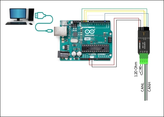
### Pin Connections (Text Reference)
```
+------------------+ +------------------+
| Arduino | | UI-MCP2515 |
+------------------+ +------------------+
| Pin 10 (CS) ---+---->| CS |
| Pin 11 (MOSI)---+---->| SI |
| Pin 12 (MISO)<--+-----| SO |
| Pin 13 (SCK) ---+---->| SCK |
| Pin 2 (INT) <--+-----| INT |
| 5V ---+---->| VCC |
| GND ---+---->| GND |
+------------------+ +------------------+
CAN Side:
+------------------+
| UI-MCP2515 |
+------------------+
| CANH --------->| CAN Bus High
| CANL --------->| CAN Bus Low
+------------------+
```
### System Wiring (with UIM342 Motor)
```
Arduino UI-MCP2515 UIM342 Motor
+----------+ +-------------+ +------------+
| CS -> 10|--------->| CS | | |
| MOSI ->11|--------->| SI | | CANH <----+---- CAN Bus High
| MISO <-12|<---------| SO | | CANL <----+---- CAN Bus Low
| SCK ->13|--------->| SCK | | V+ <----+---- 24V DC
| INT <-2 |<---------| INT | | GND <----+---- GND
| 5V |--------->| VCC | | |
| GND |--------->| GND | +------------+
+----------+ +-------------+
```
> **Note**: Connect a 120Ω termination resistor between CANH and CANL at both ends of the CAN bus for reliable communication.
---
## Quick Start
This section explains how to quickly build and run a motor system consisting of UIM342 motors and 1 UI-MCP2515 module with Arduino.
### Required Materials
| Item | Qty | Description |
|------|:---:|-------------|
| UIM342 Series Motor | 1+ | CAN bus smart motor |
| Arduino UNO (or compatible) | 1 | Microcontroller board |
| UI-MCP2515 Module | 1 | SPI to CAN gateway |
| 24V DC Power Supply | 1 | For motor power |
| USB Cable | 1 | For Arduino programming |
| Arduino IDE | 1 | Development environment |
### Step 1 — Install Arduino IDE
Visit the official Arduino website: [arduino.cc](https://www.arduino.cc/en/software/)
Download and install the version compatible with your operating system.
### Step 2 — Download Sample Code
1. Visit [uirobot.com](https://uirobot.com)
2. Navigate to **Support → Download Center**
3. Download the **UI-MCP2515** sample code package
4. Extract the downloaded ZIP file
### Step 3 — Wire the Hardware
1. Connect UI-MCP2515 to Arduino per the wiring diagram above
2. Connect CANH/CANL to the UIM342 motor controller
3. Connect 24V DC power supply to the motor
4. **Double-check all wiring before powering on**
### Step 4 — Add Required Libraries
In Arduino IDE:
1. Navigate to **Sketch → Include Library → Add .ZIP Library**
2. Add the following libraries:
- `arduino-mcp2515-master.zip` — For MCP2515 CAN communication
- `m_UIrobotConfig.zip` — For UIM342 motor configuration
### Step 5 — Upload Code to Arduino
1. Open the sample `.ino` project file
2. Select the correct **Board** and **Port** in Tools menu
3. Click **Verify** to compile the code
4. Click **Upload** to upload to Arduino
### Step 6 — Open Serial Monitor
1. Once uploaded, open **Serial Monitor** from the upper-right corner
2. Set baud rate to **2,000,000** (or as specified in the sample code)
3. Observe the output to verify communication
### Default Parameters
| Parameter | Default Value |
|-----------|---------------|
| CAN Baud Rate | 500 Kbps |
| UIM342 Node ID | 5 |
| SPI Clock | 8 MHz |
| MCP2515 Crystal | 16 MHz |
---
## Sample Code
```cpp
#include <SPI.h>
#include <mcp2515.h>
#define CS_PIN 10
struct can_frame canMsg;
MCP2515 mcp2515(CS_PIN);
void setup() {
Serial.begin(115200);
mcp2515.reset();
mcp2515.setBitrate(CAN_500KBPS, MCP_8MHZ);
mcp2515.setNormalMode();
Serial.println("UI-MCP2515 Initialized");
}
void loop() {
// JOG command: speed 500 RPM
canMsg.can_id = 0x05; // UIM342 Node ID (default = 5)
canMsg.can_dlc = 8;
canMsg.data[0] = 0x1D; // JV (Jog Velocity)
canMsg.data[1] = 0xF4; // Speed low byte (500 = 0x01F4)
canMsg.data[2] = 0x01; // Speed high byte
canMsg.data[3] = 0x00;
canMsg.data[4] = 0x00;
canMsg.data[5] = 0x00;
canMsg.data[6] = 0x00;
canMsg.data[7] = 0x00;
mcp2515.sendMessage(&canMsg);
delay(100);
// Send BG (Begin Motion)
canMsg.data[0] = 0x16; // BG command
canMsg.data[1] = 0x00;
canMsg.data[2] = 0x00;
canMsg.data[3] = 0x00;
canMsg.data[4] = 0x00;
canMsg.data[5] = 0x00;
canMsg.data[6] = 0x00;
canMsg.data[7] = 0x00;
mcp2515.sendMessage(&canMsg);
delay(2000);
}
```
---
## CAN Bus Precautions
:::warning
**WARNING**
- Avoid star connections. When CAN cable length exceeds 20 meters, dedicated CAN cables should be used. The length of branch cable to each node should not exceed 20 cm.
- It is recommended to connect a 120-ohm terminal resistor at both ends of the CAN bus.
- **Strictly avoid hot-plugging while power is on**. Hot-plugging may lead to ground loss, causing burnout of multiple devices.
- Connect all devices to a common ground.
:::
---
## Safety Precautions
| Precaution | Consequence of Neglect |
|------------|----------------------|
| Do not use in humid, corrosive, flammable gas environments or near flammable substances | Fire / Malfunction |
| Do not use the wire when soaked in oil/water | Fire / Malfunction |
| Do not frequently power on/off | Malfunction |
| Never modify, disassemble or repair by yourself | Fire / Malfunction |
| Power supply voltage must meet product requirements | Malfunction |
| Cut off power when not in use for long time | Fire / Malfunction |
---
## Video Tutorial
:::video[How to Control UlM342 CANBUS Servo Stepper Smart Motors Using Arduino+ Ul-MCP2515](https://www.youtube.com/watch?v=GLb7F3KFpPc)
:::
---
## Downloads
- 💻 [MCP2515 Datasheet](https://www.microchip.com/wwwproducts/en/MCP2515)
- 💻 [Arduino CAN Library](https://github.com/coryjfowler/MCP_CAN_lib)
- 📖 [StepEva3 User Manual V4.7 (PDF)](https://www.uirobot.com/uploads/files/Manual_StepEva3%20V4.7.pdf)
- 📖 [uirSDK3 User Manual V4.7 (PDF)](https://www.uirobot.com/uploads/files/f30fdec2ef52855e328edf9abcbd1d4e.pdf)
---
## Related Documents
- [UIM342 CAN Bus Smart Servo Stepper Motor Controller](/docs/uim342)
- [UIM2513 RS232-CAN Gateway](/docs/uim2513)
- [UIM2523 Ethernet-CAN Gateway](/docs/uim2523)
- [CAN Bus Motion Control Gateways](/docs/motion-control-gateway)
- [Quick Start Guide](/docs/quick-start)
- [Arduino CAN Bus Examples](/docs/arduino-examples)
---
*Last Updated: 2026-06-29 | Based on Application Note AN250903*