CAN Bus Compact I/O Modules
UIROBOT CAN bus compact I/O modules — 8/16 channel digital input and output expansion for distributed control systems.
# CAN Bus Compact I/O Modules — Quick Overview
> Product lineup, system architecture, and selection guide for UIM0808/UIM1616 I/O modules
---
## Product Lineup
| Model | Digital Inputs | Digital Outputs | Output Current | Supply Voltage | Dimensions |
|-------|---------------|----------------|---------------|---------------|------------|
| UIM0808 | 8 ch (NPN) | 8 ch (MOSFET) | 500 mA / ch | 12–24 VDC | 78 × 68 × 12 mm |
| UIM1616 | 16 ch (NPN) | 16 ch (MOSFET) | 500 mA / ch | 12–24 VDC | 120 × 68 × 12 mm |
---
## Key Features
:::grid{cols=2 style=card}
**DSP Control System**
Robust hardware platform with fault tolerance and fail-safe user interface.
**Digital Filtering**
Noise-immune input processing with change-of-state notification.
**SDK Support**
Complete SDK with DLL, LIB, SO files. C++ and C# sample codes included.
:::
### Input Ports
- Up to 16 digital input ports (NPN type)
- 1 quadrature encoder interface
- 1500V photoelectric isolation
- ESD protection
### Output Ports
- Up to 16 digital output ports
- 500 mA output current per port
- Max total output current: 4000 mA
- 1500V photoelectric isolation
- ESD protection
- Overheat, overload, short circuit, overvoltage protection
- Current limiting
### CAN Networking
- Active CAN 2.0, 1 Mbps max
- 1500V photoelectric isolation
- Support 3 types of IDs: Node ID, Group ID, Global ID
---
## UIM0808 — 8-Channel I/O Module
The UIM0808 provides 8 digital inputs and 8 digital outputs in a compact housing. It communicates over CAN 2.0 and is designed for applications requiring moderate I/O density.
### Specifications
| Parameter | Specification |
|-----------|---------------|
| Supply Voltage | 12–24 VDC |
| Digital Inputs | 8 channels, NPN type |
| Input Voltage Range | 0–24 VDC |
| Digital Outputs | 8 channels, MOSFET push-pull |
| Output Current | 500 mA per channel |
| Max Total Output Current | 4000 mA |
| Isolation | 1500V (optocoupler) |
| CAN Protocol | Active CAN 2.0 |
| CAN Baud Rate | Max. 1 Mbps |
| Dimensions | 78 × 68 × 12 mm |
| Operating Temp | -40°C ~ 85°C |
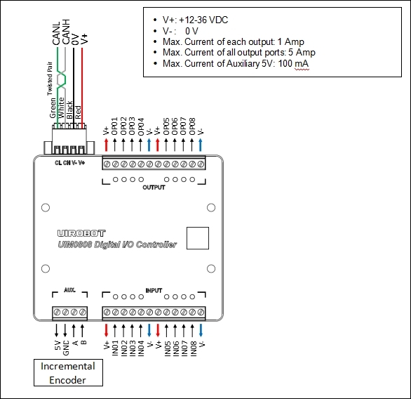
### Wiring Diagram
---
## UIM1616 — 16-Channel I/O Module
The UIM1616 doubles the I/O density with 16 digital inputs and 16 digital outputs. It shares the same CAN bus protocol and 1ms scan cycle as the UIM0808, making it easy to mix both modules on the same network.
### Specifications
| Parameter | Specification |
|-----------|---------------|
| Supply Voltage | 12–24 VDC |
| Digital Inputs | 16 channels, NPN type |
| Input Voltage Range | 0–24 VDC |
| Digital Outputs | 16 channels, MOSFET push-pull |
| Output Current | 500 mA per channel |
| Max Total Output Current | 4000 mA |
| Isolation | 1500V (optocoupler) |
| CAN Protocol | Active CAN 2.0 |
| CAN Baud Rate | Max. 1 Mbps |
| Dimensions | 120 × 68 × 12 mm |
| Operating Temp | -40°C ~ 85°C |
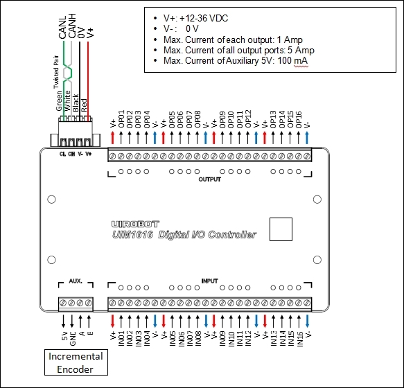
### Wiring Diagram
---
## Comparison
| Feature | UIM0808 | UIM1616 |
|---------|---------|---------|
| Digital Inputs | 8 | 16 |
| Digital Outputs | 8 | 16 |
| Input Type | NPN | NPN |
| Output Current | 500 mA / ch | 500 mA / ch |
| Max Total Current | 4000 mA | 4000 mA |
| Supply Voltage | 12–24 VDC | 12–24 VDC |
| Isolation | 1500V | 1500V |
| Encoder Interface | Yes | Yes |
| Dimensions | 78 × 68 × 12 mm | 120 × 68 × 12 mm |
| Best For | Moderate I/O | Full-scale expansion |
---
## Instruction Set Summary
### System Instructions
| Mnemonic | Control Word | Function | Description |
|----------|--------------|----------|-------------|
| `PP[i]` | 0x01 | Set/Get | Protocol Parameters |
| `IE[i]` | 0x07 | Set/Get | Information Enable |
| `ML` | 0x0B | Get | Model Information |
| `SN` | 0x0C | Get | Serial Number |
| `ER[i]` | 0x0F | Clear/Get | Error Report |
| `QE[i]` | 0x3D | Set/Get | Quadrature Encoder |
| `SY[i]` | 0x7E | Set | System Operation |
### I/O Instructions
| Mnemonic | Control Word | Function | Description |
|----------|--------------|----------|-------------|
| `TG[i]` | 0x35 | Set/Get | Input Trigger Type |
| `DI` | 0x37 | Set/Get | Digital Input/Output |
### Auxiliary Encoder Instructions
| Mnemonic | Control Word | Function | Description |
|----------|--------------|----------|-------------|
| `SP` | 0x1E | Get | Encoder Speed |
| `PR` | 0x1F | Get | Encoder Periodical Counts |
| `PA` | 0x20 | Get | Encoder Counts |
| `OG` | 0x21 | Set | Clear Encoder Counter |
### Notification Instructions
| Mnemonic | Control Word | Function | Description |
|----------|--------------|----------|-------------|
| `RT` | 0x5A | Auto Sent | Real-Time Information |
---
:::tip
All I/O modules use the same CAN 2.0B protocol as UIROBOT motor controllers, allowing seamless integration in a unified CAN bus network.
:::
## Quick Start
### Step 1 — Choose Your Module
| If you need... | Use... |
|----------------|--------|
| Up to 8 DI + 8 DO | UIM0808 |
| Up to 16 DI + 16 DO | UIM1616 |
### Step 2 — Connect Hardware
1. Connect power supply (12–24 VDC)
2. Wire CANH and CANL to the CAN bus (twisted pair recommended)
3. Connect sensors to digital inputs, loads to digital outputs
4. **Double-check all wiring before powering on**
### Step 3 — Using StepEva3 Software
1. Download and run the Windows control panel **StepEva3**
2. Select **UIM2513 (RS232-CAN)** gateway
3. Select the I/O module to operate from the device list
4. Use the I/O control panel to read inputs and control outputs
---
## CAN Bus Precautions
> **WARNING**
- Avoid star connections. When CAN cable length exceeds 20 meters, dedicated CAN cables should be used. The length of branch cable to each node should not exceed 20 cm.
- UIM2513 has a built-in terminal resistor, which can be activated by the toggle switch. It is recommended to connect a 120-ohm terminal resistor to the other end of the CAN cable.
- **Strictly avoid hot-plugging while power is on**. Hot-plugging may lead to ground loss, causing burnout of multiple UIM devices.
- Connect all UIM devices to a common ground.
---
## Safety Precautions
| Precaution | Consequence of Neglect |
|------------|----------------------|
| Do not use in humid, corrosive, flammable gas environments or near flammable substances | Fire / Malfunction |
| Do not use the wire when soaked in oil/water | Fire / Malfunction |
| Do not frequently power on/off | Malfunction |
| Never modify, disassemble or repair by yourself | Fire / Malfunction |
| Power supply voltage must meet product requirements | Malfunction |
| Cut off power when not in use for long time | Fire / Malfunction |
---
## Downloads
- 📖 [UIM1616 User Manual V4.7 (PDF)](https://www.uirobot.com/uploads/files/Manual_UIM1616%20V4.7.pdf)
- 📖 [StepEva3 User Manual V4.7 (PDF)](https://www.uirobot.com/uploads/files/Manual_StepEva3%20V4.7.pdf)
- 📖 [uirSDK3 User Manual V4.7 (PDF)](https://www.uirobot.com/uploads/files/f30fdec2ef52855e328edf9abcbd1d4e.pdf)
---
## Related Products
| Product | Description |
|---------|-------------|
| UIM342 | CAN bus smart motor controller |
| UIM342A | CAN bus smart motor controller (absolute encoder) |
| UIM2513 | RS232 to CAN gateway |
| UIM2523 | Ethernet to CAN gateway |
| UIC320A | USB to CAN 2.0B adapter (isolated) |
| MMC90X | Miniature motion control computer |
---
## Related Documents
- [UIM1616 Digital I/O Controller — Technical Reference](/docs/uim1616)
- [UIM342 CAN Bus Smart Servo Stepper Motor Controller](/docs/uim342)
- [UIM342A CAN Bus Smart Servo Stepper Motor Controller](/docs/uim342a)
- [Quick Start Guide](/docs/quick-start)
---
*Last Updated: 2026-06-23 | Based on UIM0808/UIM1616 User Manual V4.7*